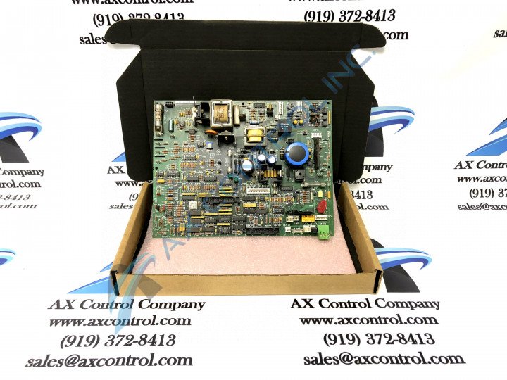
About the DS200IMCPG1CDB
This DS200IMCPG1CDB Power Supply Interface Board is an important part of its Mark V Series, as explained above. The Mark V Series was originally developed and produced by the trusted industry giant General Electric, as a series of turbine control systems and turbine control system component parts. It is important to realize that this DS200IMCPG1CDB Power Supply Interface Board is not actually a base-produced version of this General Electric Mark V Series product, as the DS200IMCPG1 Power Supply Interface Board exists without the three significant product revisions made to this specific PCB.
Hardware Tips and Specifications
Unfortunately for our sake, this DS200IMCPG1CDB Power Supply Interface Board's specific hardware makeup and specifications need to be partially theorized, given the lack of pertinent original instructional manual materials available for research purposes on the internet. With this being said, is quite lucky that this is categorized as a General Electric product, as its DS200IMCPG1CDB functional product number reveals a lot about this particular PCB. In combination with Mark V Series materials that do exist, a customized product page for this DS200IMCPG1CDB Power Supply Interface Board is possible. The GE IAC2000I Power Supply Interface Board DS200IMCPG1CDB can be connected through a cable to the DS200SDCC Drive Control Board. In order to initiate this connection, one must connect the cable to the 1PL connector on the Drive Control Board. The GE IAC2000I Power Supply Interface Board DS200IMCPG1CDB is engineered to operate under conditions with high-voltage current and it is equipped with eight fuses to protect it from overcurrent. It is important to check the fuses if you suspect one is blown; you can easily locate the fuses and check the contact in each fuse and see if it is intact.
To replace a fuse you must remove all current to the drive. The best practice is to remove the fuses of the power supplies that provide power to the drive; in order to avoid potentially lethal surface voltages. The next step after removing power from the DS200IMCPG1CDB board is to use a testing device to check for the presence of power. Make sure the tester is appropriately calibrated for the purpose and is approved by a certifying organization, and that the tester probes are in good condition and any insulation is not worn or frayed. When you are sure no current is present, General Electric instructional materials suggest to use one hand to remove the blown fuse from the connector, before pressing an identical fuse into the connector.


