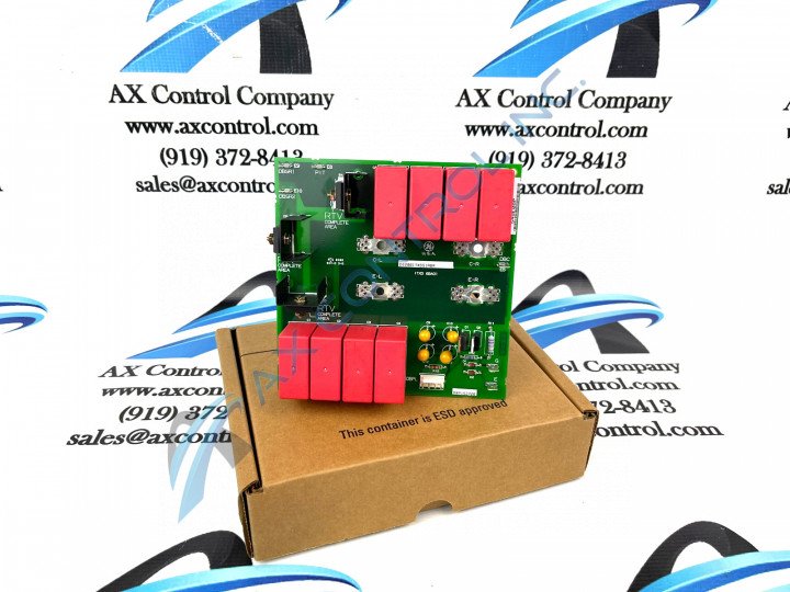
About the DS200ITXDG1ABA
The DS200ITXDG1ABA board is labeled as a Dynamic Braking Snubber Board as part of the Mark V series made by General Electric. The Mark V Series that this DS200ITXDG1ABA product offering belongs to is one of the final General Electric Mark product series to adopt the Speedtronic control system technology into its various offerings, and exists as a legacy product series given its eventual manufacturing discontinuation in the many years following its initial release. This DS200ITXDG1ABA printed circuit board or PCB for short is not the originally-developed product of its specific Mark V Turbine Control System Series functional role; that would actually be the DS200ITXDG1 parent Dynamic Braking Snubber Board notably missing all three of this DS200ITXDG1ABA PCB's three significant product revisions. The assembly of this DS200ITXDG1ABA PCB has been specifically altered through its adoption of an A-rated primary functional revision, a B-rated secondary functional revision, and an A-rated artwork configuration revision.
Hardware Tips and Specifications
The operation required for the IXTD board is provided through the circuits of the connected power supply/interface board (IMCP). When the IMCP and the IXTD boards are connected they are connected through a four-pin connector. When the board is mounted it will be mounted externally and must be sized to meet the worst-case switching demands of the dynamic braking IGBT. The purpose of snubber boards is to be used to limit the voltage transients across the IGBTs and through all known operating conditions of the drive. Another ability of the DS200ITXDG1ABA board is to condition outputs from the IGBT Gate Driver Board to be able to match the electrical properties of the AT frame drives. There are variable and constant torque applications for the AT frame drives. The drive-rated output current for the variable torque applications is five hundred ARMS.
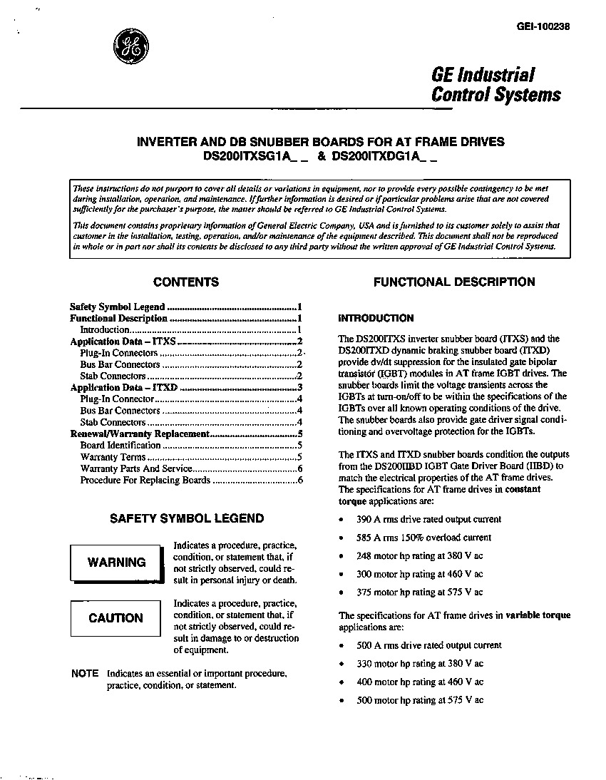
There are three connector types for the DS200ITXDG1ABA board; bus bar I/O connectors, input connectors for the DBPL, and board stab connectors. There are different pin numbers, nomenclatures, as well as descriptions for all of these connector types, as detailed in depth in the DS200ITXDG1ABA instructional manual attached above for your convenience. The bus bar I/O connectors and stab I/O connectors have directions as well. An example of two pins related to the stab I/O connectors are the E-6 and E-9 connectors, both are output connectors. The E-6 connector is the DB IGBT gate signal, and the E-9 connector is the connection for the external snubber resistor. The singular plug-in connector made available to the assembly of this DS200ITXDG1ABA Dynamic Braking Snubber Board is well-discussed in pertinent General Electric instructional manual materials as well. This connector is accompanied by the DBPL factory-printed nomenclature label, and connects this DS200ITXDG1ABA product offering to its accessible IMCP cousin printed circuit board product within the greater Mark V Series automated drive assembly. For your convenience, this DS200ITXDG1ABA PCB's plug-in connector positioning is additionally described in available instructional materials. Before making any singular ultimate purchase decision on this DS200ITXDG1ABA Dynamic Braking Snubber Board, it is important to realize that its originally-introduced performance specifications and dimensions have no doubt been altered by its acceptance of a full three-fold revision history.


