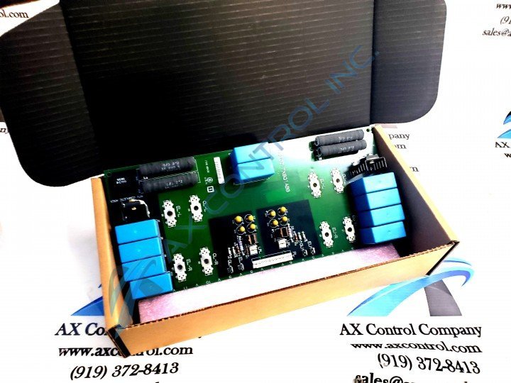
About the DS200ITXSG1A
This DS200ITXSG1A Inverted Snubber Board is a crucial member of the Mark V Turbine Control System Series developed by General Electric, as mentioned above. With this in mind, it is important to contextualize each individual hardware component made available to the DS200ITXSG1A Inverter Snubber Board within the greater intended functionality of the Mark V Series product offering. Luckily enough for our sake, this DS200ITXSG1A Inverter Snubber Board has a plethora of available instructional manual materials detailing its specific function. The Mark V Series that this Hardware Tips and Specifications printed circuit board product offering exists as a component member of has specific applications in the control and management systems of compatible and popular wind, steam, and gas turbine automated drive assemblies, as indicated by the full extended series name attached above. This DS200ITXSG1A PCB's greater Mark V Series, while applicable to newer-developed turbine applications, must still be considered obsolete as a whole, given the broad-scale manufacturing discontinuation that took place in one of the many years beyond its initial rollout due to a manufacturer-realized functional series obsolescence.
Hardware Tips and Specifications
According to these GE materials, this DS200ITXSG1A Inverter Snubber Board was specifically manufactured for use in A frame drives, as it helps to provide both dv and dt suppression for IGBT modules in IGBT-led drive assemblies. In ordered to achieve its intended functionality, this DS200ITXSG1A Inverter Snubber Board makes use of an elevated number of hardware components. The GE Inverter Snubber Board DS200ITXSG1A features one 8-pin connector, two 2-pin connectors, and multiple test points. It is also populated with four capacitors. Additionally, a singular 12-pin connector seems to have been adopted for use with this Mark V Series product offering, specifically in order to interface with the IIBD board within the same Mark V Series drive assembly. Different specifications exist for this DS200ITXSG1A device's AT Frame Drives, given their various different applications. When applied in constant torque applications, this DS200ITXSG1A PCB's AT Frame Drive will have a different set of specifications as compared to its placement in a variable torque application. Before making a purchase decision on this DS200ITXSG1A Inverter Snubber Board, it is important to realize that this is a modified General Electric product, as it has been changed from its original DS200ITXSG1 parent product status through its insertion of a singular, A-rated functional product revision. This piece of information was revealed upon a breakdown of the functional DS200ITXSG1A product number, which includes other details such as:
- A DS200 normal assembly type
- A Salem, Virginia original factory location
- The ITXS functional acronym
- A normal style of PCB coating
- A group one Mark V Series grouping
The GE Inverter Snubber Board DS200ITXSG1A generates heat, that if allowed to build up, can cause sensors in the drive to produce an error condition to keep the drive from overheating. The electrical components or the motor might be damaged if the drive is allowed to overheat. Also, a safety hazard that leads to fire can occur. If the overheat condition occurs, the drive is automatically shut off and you must take action to rectify the situation. When the drive is automatically shut off to prevent an overheat condition, it is called a trip condition. A trip condition causes an error message that displays on the control panel display. This DS200SDCIG1A printed circuit board's internal processes are crucially supported by another Mark V Series device available to our extended new and reconditioned inventory here. To be specific, this DS200SDCIG1A Inverter Snubber Board's entire operation is controlled through the use of pieces of circuitry available on the base printed circuit board of the IMCP Power Supply and Interface Board. The IMCP Board is also available for both repair and replacement here today, in a number of different revision styles for your convenience. Just give it a quick search in the AX Control inventory search bar above. As determined once again in the DS200SDCIG1A instructional manual made available above, this DS200SDCIG1A device makes use of four total stab-style connectors in its assembly; each of which should be accompanied by their own individual factory-printed nomenclature labels. This DS200SDCIG1A PCB's stab-style connectors include the EU, GU, EL, and GL connectors connected to upper and lower Insulated Gate Bipolar Transistor gate emitter circuits.


