About the DS200LDCCG1A
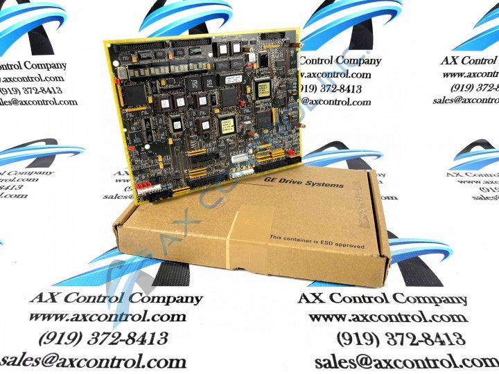
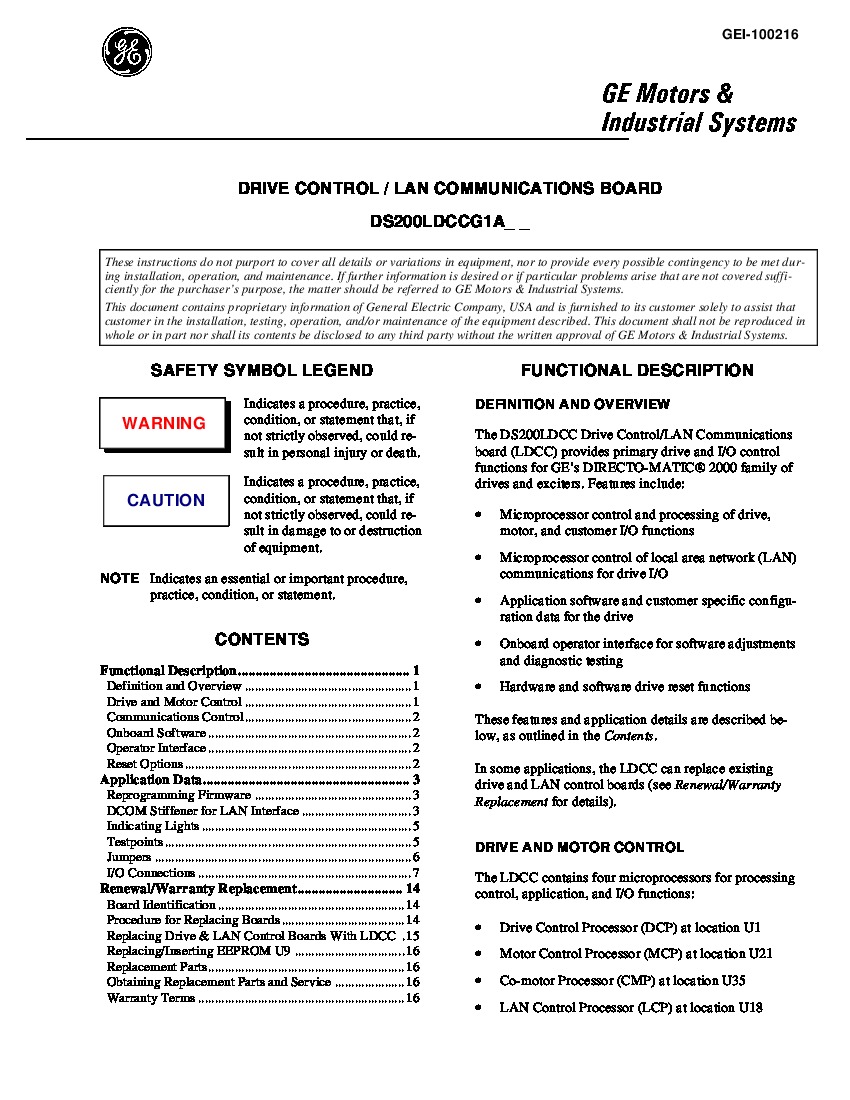
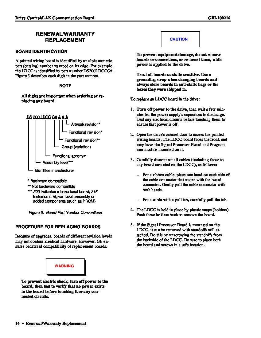
The General Electric DS200LDCCG1A is a base level control board from the Mark V series. This board is a drive control and LAN communications board (LDCC). Specifically, it was designed to provide drive and I/O controls to GE family of DIRECTO-MATIC 2000 exciters and drives. Onboard features of this board include microprocessor controlled LAN (local area networks) communications, controlled drive and motor processing, operator interface, and complete drive resets. The Mark V Series that this DS200LDCCG1A product offering belongs to has specific applications in the control and management systems of steam, wind, and gas turbine automated drive assemblies, and is considered a General Electric legacy series given its original manufacturer's production discontinuation in the years following its original release. While this DS200LDCCG1A PCB is definable as a Drive Control and LAN Communications Board in its own right, the original product of this intended functionality to exist within the Mark V Turbine Control System Series is the DS200LDCCG1 parent printed circuit board missing this DS200LDCCG1A product's A-rated functional product revision.
Hardware Tips and Specifications
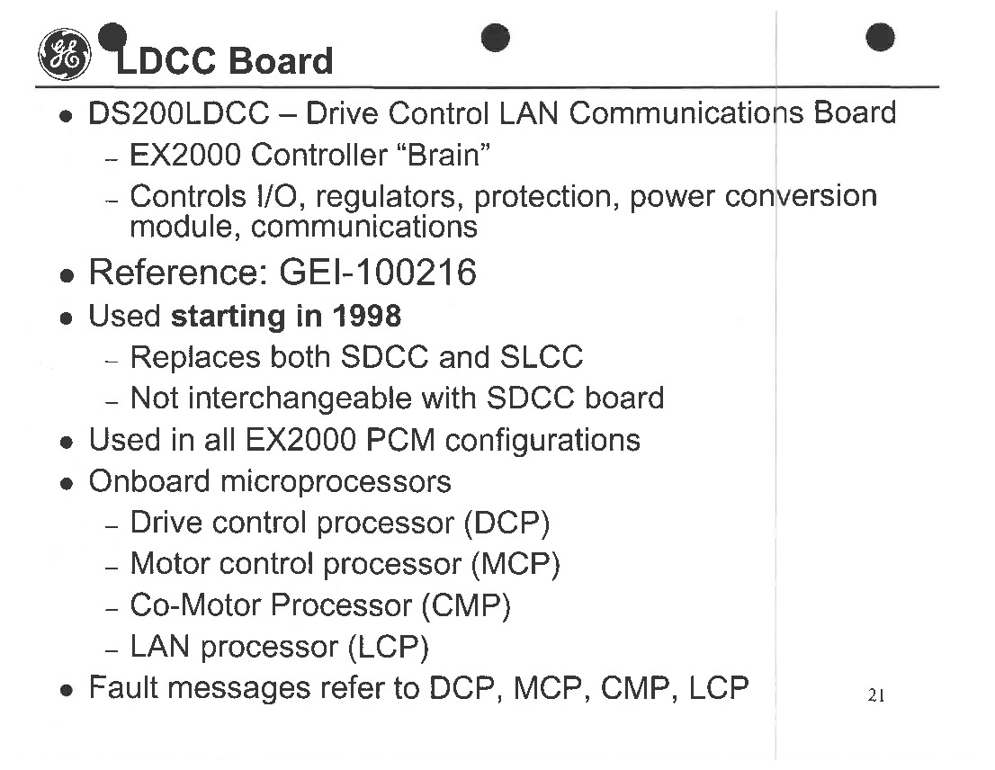
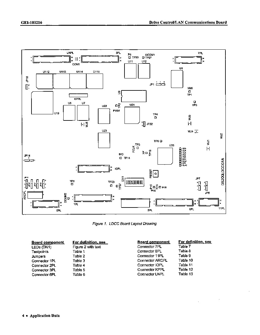
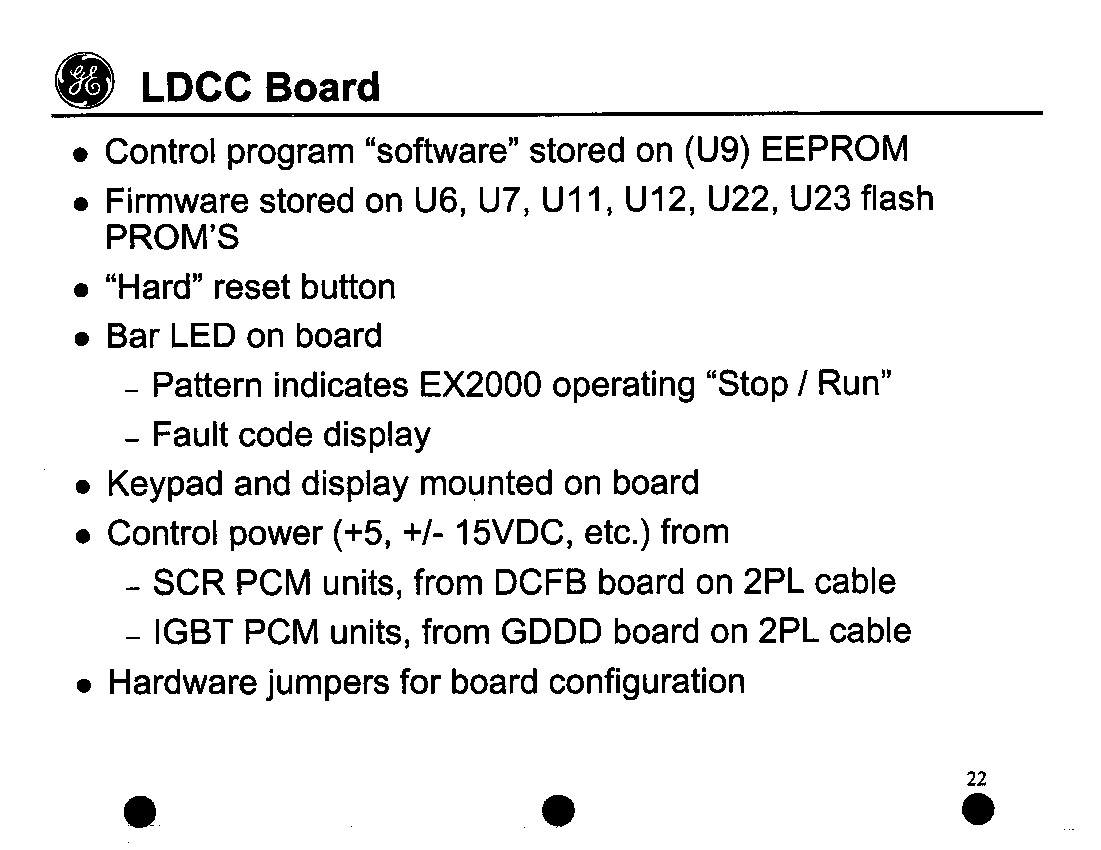
As with any Mark V Turbine Control System Series product available here, the DS200LDCCG1A Drive Control/LAN Communications Board makes use of its own series of functionality-introducing hardware component inclusions and specifications. Four microprocessors are located on the board, providing DS200LDCCG1A with a sweeping coverage of I/O and drive control. The drive control processor (DCP) is located on the DS200LDCCG1A board as position U1. This processor provides integrated I/O peripherals, offering abilities like timers and decoders. The second processor in this DS200LDCCG1A device's assembly is a motor control processor (MCP), recognized on the board as U21. Motor control circuitry and I/O (analog and digital) communications are available with this processor. U35 is the location of the co-motor processor (CMP). Only used when additional processing is required, this section works to perform advanced mathematics the MCP cannot compute. The final processor found on the DS200LDCCG1A PCB's base circuit board is the LAN control processor (LCP) in position U18. Five bus systems (DLAN+, DLAN, Genius, CPL, and C-bus) are accepted by this processor. A user interface system (Programmer) is available to the DS200LDCCG1A PCB with an attached alphanumeric keypad; this interface system allows users to view and adjust system settings and diagnostics.
Two different types of LED indicators are included in this DS200LDCCG1A circuit board's assembly, in the form of both Programmer digital display and the DN1 bar graph LEDs. These LEDs have been named for the specific application or DS200LDCCG1A board function that they diagnose, and offer a series of different LED blinking rates detailing different DS200LDCCG1A board functional faults, as described in the DS200LDCCG1A instructional manual available in the manuals tab above. A unique characteristic of these LEDs in the DS200LDCCG1A Drive Control and LAN Communication Board's external assembly is their ability to configure for the display-ment of coarse display drive variables, which is achievable through configuration of this DS200LDCCG1A PCB's customizable software jumper, again as explained in this DS200LDCCG1A product's attached instructional manual. DS200LDCCG1A includes manufacturer provided installation parameters that should be met to ensure the board operates properly. A complete guide to wiring and installing the board into its drive is available in both the drive’s manual and datasheet. Technical support for this board was originally provided by General Electric.Our knowledgeable staff at AX Control is happy to help with all of your automation needs. To receive current prices on all parts and repairs, please contact our sales team by phone or email.


