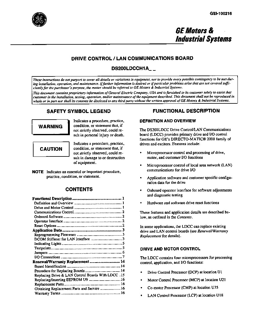
About the DS200LDCCH1ARA
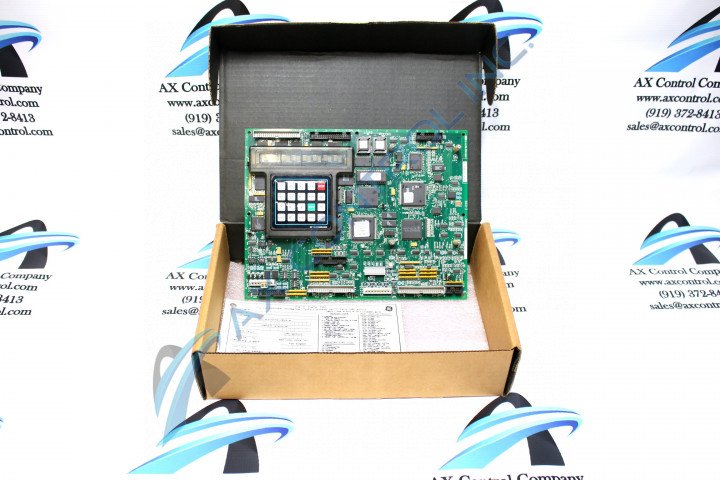
This DS200LDCCH1ARA printed circuit board was originally manufactured for use in the Mark V Turbine Control System Series by General Electric. The Mark V Series, as you can probably tell by its full name, has specific applications in the control and management systems of compatible gas, steam and wind turbine automated drive assemblies, and is considered a General Electric legacy series due to its eventual manufacturing discontinuation in the years following its original release. While a General Electric legacy series, the Mark V Turbine Control System Series that this DS200LDCCH1ARA product offering belongs to is also one of the final General Electric product series to incorporate the patented Speedtronic control system technology into its offerings. This DS200LDCCH1ARA printed circuit board or PCB for short is truly better-definable by its official functional product description as a Drive Control/LAN Communications Board, as it appears in original DS200LDCCH1ARA instructional manual materials. This DS200LDCCH1ARA PCB is not the original product of its functionality to feature in the Mark V, however; that would be the DS200LDCCH1 Drive Control/LAN Communications Board notably missing this DS200LDCCH1ARA product's three significant revisions.
Hardware Tips and Specifications
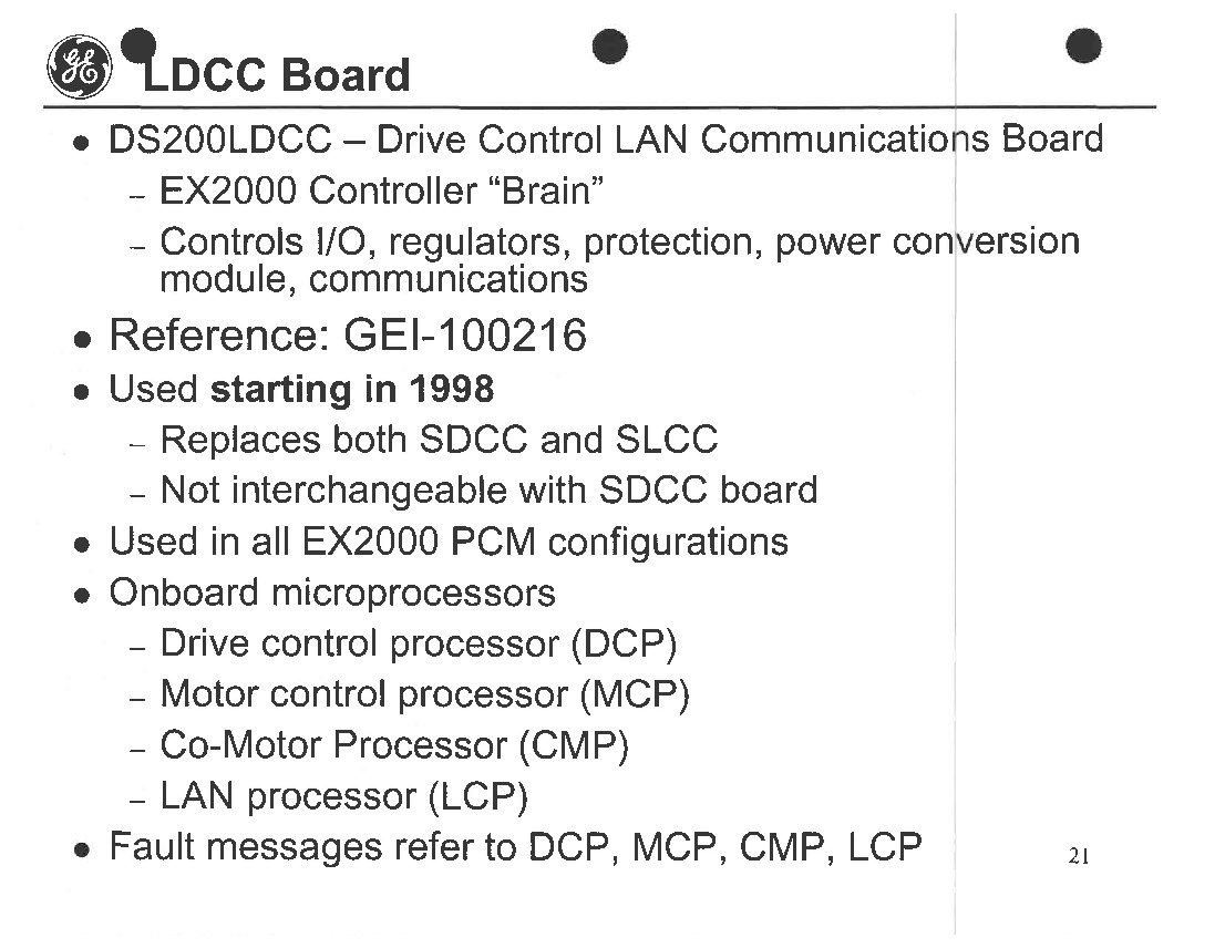
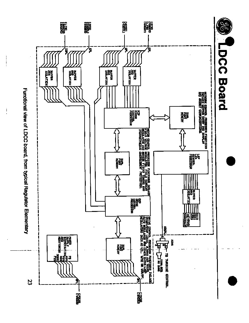
The GE Drive Control/LAN Communications Board DS200LDCCH1ARA features multiple microprocessors that provide control for the drive, motor, and I/O functions. It also provides control for the LAN network. This DS200LDCCH1ARA printed circuit board product offering's voltage limitation and suppression is generally handled by its normal Mark V Series assembly's inclusion of a standardized series of voltage-suppressing components such as transistors, resistors, capacitors, and diodes. The GE Drive Control/LAN Communications Board DS200LDCCH1ARA is populated with programmable memory that comes from the factory with a predefined configuration. However, the configuration can be edited to meet the needs of the site. To edit the configuration, you must have a laptop or other device and a serial cable to connect to the serial port on the laptop and the port on the Drive Terminal board in the drive. The serial cable must be 6 feet in length or less. The DS200LDCCH1ARA also is populated with a display screen for use with an optional handheld keypad for making edits to the configuration and accessing the diagnostic tools available on the drive. Eight total testpoints exist in the assembly of this DS200LDCCH1ARA printed circuit board; specially included for diagnostic purposes and functional fault recognition. The testpoints made available to this DS200LDCCH1ARA Drive Control/LAN Communications Board include:
- The TP8 Drive Type-Specific Motor Current Test point
- The TP25 Positive Power Supply Test Point
- The TP26 Negative Power Supply Test Point
- The TP27 & TP31 Common Reference Signal Test Points
- The TP29 Input Line Frequency Test Point
- The TP30 Regulated Positive Volt Power Supply Test Point
- The TP37 Drive Type-Specific Voltage Test Point
All of the various test points listed above and in the assembly of this DS200LDCCH1ARA product have been named through a combination of their Mark V Series test point numbers and specific testing applications. The test point numbers for each of these test points is different from each of their respective factory-printed nomenclature labels; these values are identified in the DS200LDCCH1ARA instructional manual attached above as well. Before making a final purchase decision on this DS200LDCCH1ARA product offering, it is important to realize it has been edited from its original un-revised performance specifications and dimensions through use of two functional revisions and an artwork revision, rated at A, R and A grades respectively. The DS200LDCCH1ARA board also has a connector that can be used to connect to the keypad. The keypad has multiple buttons and a two-line display. Use the keypad to make minor adjustments to the configuration file but use the laptop to make major changes to the configuration. To begin this process, it is crucial to first remove all power to the drive and verify that power is removed by testing the drive for power. Connect the serial cable to the port on the Drive Terminal board and to the laptop. Make sure the serial port on the laptop is configured properly. Download the editing software to the laptop and install it. Follow the instructions on the screen to access the configuration and edit the file.


