In Stock
DS200LPPAG1AAA Image One
3 year warranty

DS200LPPAG1AAA Image 1
DS200LPPAG1AAA Image 2
DS200LPPAG1AAA Image 3
DS200LPPAG1AAA Image 4

DS200LPPAG1AAA

    Varying star amount pictures Varying star amount pictures Varying star amount pictures Varying star amount pictures Varying star amount pictures
  • 4.93 (14)
  • Click a star to rate this product
    Varying star amount pictures Varying star amount pictures Varying star amount pictures Varying star amount pictures Varying star amount pictures
  • 4.93 (14)
  • Click a star to rate this product
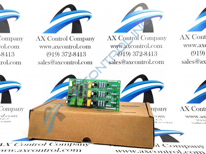
The General Electric DS200LPPAG1AAA Line Protection Panel Board was originally manufactured for use in the Mark V Turbine Control System Series.

AVAILABILITY:

IN STOCK
SHIPS IN 3-5 DAYS

Sell Surplus: Have a DS200LPPAG1AAA to sell? Sell Now
Exchange Credit: Learn more about our exchange credit program
  • Part Number: DS200LPPAG1AAA
  • SKU: DS200LPPAG1AAAGBTC
  • Manufacturer: GE Boards & Turbine Control
  • Series: Mark V DS200

DS200LPPAG1AAA Technical Specifications

Part Number DS200LPPAG1AAA
Series Mark V
Manufacturer GE General Electric
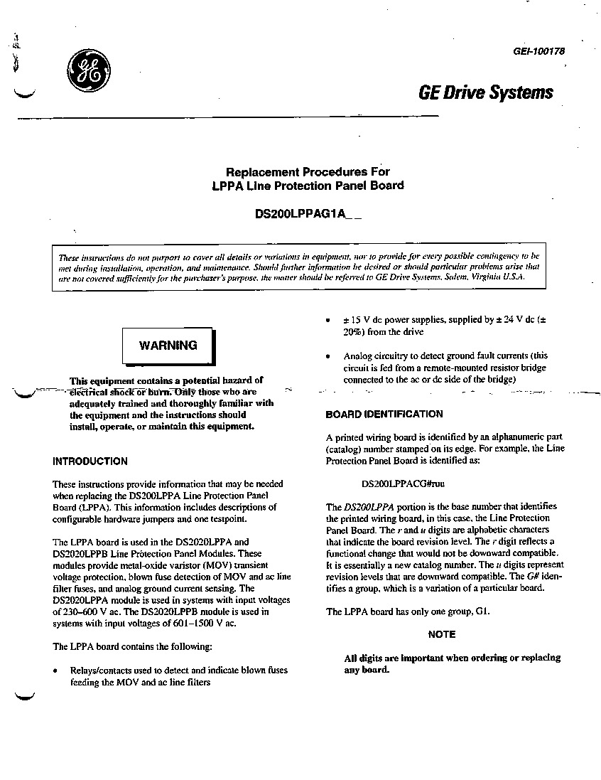
Instruction Manual GEI-100178
Product Type Line Protection Panel Board
Functional Acronym/Abbreviation LPPA
System Input Voltage 200-600 VAC
Group Revision G1

Product Description

This DS200LPPAG1AAA product offering is a printed circuit board originally manufactured for placement in General Electric's now-obsolete Mark V Turbine Control System Series, as revealed above. The Mark V Series that this DS200LPPAG1AAA product belongs to is obsolete given its status as a legacy series discontinued for manufacture in the years following its initial rollout. While this DS200LPPAG1AAA PCB's greater Mark V Series may exist as a legacy series, it is also one of the final General Electric product series to make use of the company's patented Speedtronic control system technology first introduced in the later 1960s. This DS200LPPAG1AAA printed circuit board or PCB for short is better-definable through its official functional product description as a Line Protection Panel Board, as included in the DS200LPPAG1AAA instructional manual attached above. This DS200LPPAG1AAA PCB is not the originally-designed product of its functionality to make an appearance within the Mark V; that would be the DS200LPPAG1 parent Line Protection Panel Board missing all three of the DS200LPPAG1AAA PCB's three significant product revisions.

Hardware Tips and Specifications

As with any Mark V Turbine Control System Series product offering, the DS200LPPAG1AAA PCB's assembly is accompanied by its own series of functionality-enhancing hardware component inclusions and specifications. The GE Line Protection Board, DS200LPPAG1AAA, features seven jumpers and two terminal blocks with three terminals on each. The jumpers are identified as JP1 through JP7. The GE Line Protection Board DS200LPPAG1AAA also contains test points. The DS200LPPAG1AAA board is installed on standoffs on another component of the drive. The signal wires that connect to the board originate on the other component. Luckily enough for the purposes of this DS200LPPAG1AAA Board personalized product page, the specific applications and functions of each jumper in this DS200LPPAG1AAA Board's assembly has been described in its originally-printed instructional manual materials. The DS200LPPAG1AAA Board's seven jumpers include:

  • The JP1, JP2, and JP3 MOV or ac line filter blown fuse indication jumpers
  • The JP4 and JP7 ac or dc side connection analog ground current sensing jumpers
  • The JP5 grounding resistor bridge voltage application jumper
  • The JP6 SCR ripple filter jumper

Each jumper in this DS200LPPAG1AAA Line Protection Panel Board's assembly has been named through a combination of their factory-printed nomenclature labels and specific DS200LPPAG1AAA Board functionality. If you suspect that the DS200LPPAG1AAA board is not functioning properly, there are several steps you can take to determine if the board is faulty. The first step is to access the diagnostic tool contained in the drive to produce a report on the health of the functions and components. The diagnostic tools are a menu selection on the control panel. Once the diagnostic report is complete, you can view it on the control panel display or download the file to a laptop. The file can be saved, and you can compare the diagnostic results before and after your repair actions.The module has a menu-driven interface one selection is to access the diagnostics. The other menu selection enables you to download and upload files from a laptop connected through a serial cable. Other menu selections are to access the sections of the drive configuration and edit the parameters. The parameters define the behavior of the drive during operation.The keypad on the DS200LPPAG1AAA contains buttons that enable the operator to control the drive directly without changing the parameters. The operator can stop and run the drive and select to speed up or slow down the drive, depending on predetermined parameters.

Frequently Asked Questions about DS200LPPAG1AAA

Are there any other group revisions available for the DS200LPPAG1AAA model?

No, the only group available on LPPA models is G1, but there are differences between the module types. This model, an LPPA board, will be used in systems with input voltages in the range of 230-600 VAC. The LPPB board, which is also a Line Protection Panel board, operates in systems with input voltages in the range of 601-1500 VAC. The different input voltages are the only differences in Line Protection Panel modules in the Mark V DS200 series. 

If the DS200LPPAG1AAA model malfunctions how should I go about replacing the board?

If the model malfunctions and must be replaced, then the power in which the board is installed must be removed, and wait for all capacitors to discharge. Remove the LPPA board from the cabinet and disconnect all of the cables. Be sure when disconnecting the cables that the individual wires from the screw terminal section are not removed from the connector. When removing the wiring connected to a stab terminal board, grasp the body of the receptacle and pull the acceptable free and not the wire. To remove the board squeeze the locking tabs on each of the four locking standoffs. 

Reviews For DS200LPPAG1AAA

Internal Review
(4.0)

One of the downsides of the LPPA board is that the voltage on which the model operates is less than the LPPB board. The LPPA board accepts an input voltage of 230-600 VAC; the LPPB board will operate on an input voltage of 601-1500 VAC. With this being true, the DS200LPPAG1AAA PCB is nevertheless well-supported by a full revision table and a thick layer of rudimentary daily wear and tear normal PCB surface coating. - AX Control Lead Technician

Repair Services For DS200LPPAG1AAA

Type Lead Time Price Action
Repair Service 1-2 weeks $365

Our highly skilled technicians can repair your DS200LPPAG1AAA. All of our repairs come with a 3 Year AX Control Warranty. Please contact us for additional information about our repair process. To receive the repair pricing and lead time listed above please process your repair order via our website. The following repair options may be available upon request:

  • 48-72hr Rush Repair
  • Detailed Repair Reports
  • AX Control Certificate of Warranty

AX Control Warranty Info

All products we sell are backed by our unparalleled warranty. A warranty certificate will be provided with your order upon request.
All PLCs, HMIs, and Turbine Control Boards: 3 Years
All AC/DC and Servo Drives: 2 Years
All Motors: 1 Year
Learn More

DS200LPPAG1AAA Manuals, White Papers, Data Sheets, and Troubleshooting