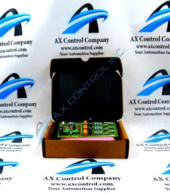
About the DS200LPPAG1ABA
This DS200LPPAG1ABA printed circuit board from General Electric is better-definable by its original instructional manual-introduced functional description as a Line Protection Board, as explained above. This DS200LPPAG1ABA GE PCB's LPPA functional abbreviation happens to line up almost exactly with this intended functional description; the only difference being the insertion of an A digit simply representing this module's assembly status in the LPPA functional abbreviation. This DS200LPPAG1ABA Line Protection Board actually does not exist as the original Line Protection Board Assembly manufactured for General Electric's Mark V Series; that would be the DS200LPPAG1ABA parent Line Protection Board that doesn't feature any one of this PCB's three significant product revisions.
Hardware Tips and Specifications
This DS200LPPAG1ABA Line Protection Board, along with any product featured in a General Electric Speedtronic Series, is equipped with its own series of specific hardware component inclusions and specifications. The GE Line Protection Board DS200LPPAG1ABA features 7 jumpers and 2 terminal blocks with 3 terminals on each block. The jumpers are identified as JP1 through JP7, as is standard with most customizable Mark V Series products. The GE Line Protection Board DS200LPPAG1ABA also contains test points. This DS200LPPAG1ABA board is installed on standoffs on another component of the drive. The signal wires that connect to the board originate on the component to which it is attached, and the dimensions of the board are is 3.5 inches by 7 inches, with it being designed to be installed with screws to another component.
General Electric offers the DS200LPPAG1ABA Line Protection Board installer with a strict series of installation guidelines. When you install the DS200LPPAG1ABA board, its factory-drilled holes align with the standoffs, allowing for the insertion of screws to secure the board. Make sure you don’t over tighten these screws because in doing so you might cause the board to crack, as the DS200LPPAG1ABA board is brittle and is easily broken. When the two components are mounted together, install them in the Mark V Series drive and secure them with screws, while reattaching the signal wires to the terminals by inserting the bare copper end of the wire into the terminal. The terminals of this DS200LPPAG1ABA Line Protection Board all have IDs that you can use to determine where to reattach the signal wires. Before you perform the installation you must be aware that static electricity can damage the board and other components. An EDS protective wrist strap can drain the static from your body and the board to a ground structure, for example a bare metal chair leg or a metal support on a workbench.


