About the DS200PANAH2
This DS200PANAH2 printed circuit board product offering, as specified just above, was originally manufactured by General Electric, specifically for placement in their Mark V Turbine Control System Series. The Mark V Series that this DS200PANAH2 printed circuit board or PCB for short belongs to, as you have probably been able to predict based off of the above-attached full extended series name, has specific applications in the management and control systems of popular and compatible steam, wind, or gas turbine automated drive assemblies. This DS200PANAH2 PCB's Mark V Series also exists as a now-defunct legacy product series that has a necessitated manufacturing discontinuation due to obsolescence take place in one of the many years past its initial General Electric release. While this DS200PANAH2 product offering's greater Mark V Series is not a well-updated or even currently-manufactured General Electric product series, it is still highly esteemed in the current automated industrial marketplace, as it exists as one of the final General Electric Mark product series to make use of their patented Speedtronic control system technology first introduced in the later 1960s behind the rollout of the Mark I Series. This DS200PANAH2 PCB is the original product of its intended Mark V Series functional role, as proven by the absence of any trailing revision-indicating digits in the DS200PANAH2 functional product number.
Hardware Tips and Specifications
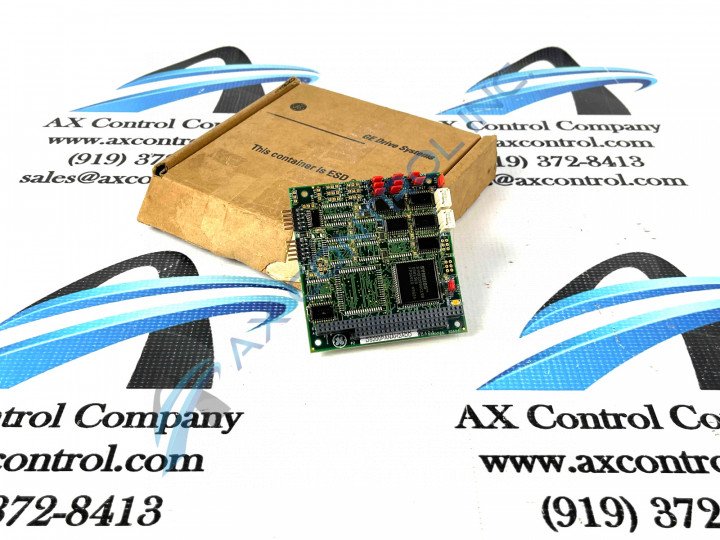
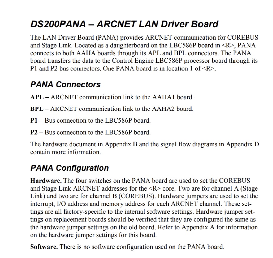
The GE ARCNET No-LAN LM Gas Turbine Control Board DS200PANAH2 features one 40-pin connector, 10 jumpers, and one 64-pin connector. The GE ARCNET No-LAN LM Gas Turbine Control Board DS200PANAH2 also has two RF FETs to amplify and adjust the signal. The RF FET components have turn screws you can use to adjust the signal. When the drive is removed from the power source, you can use a screwdriver inserted into the RF FET transistors to make adjustments. When the electrical power is restored you can test the board and determine if further adjustments are called for. As this DS200PANAH2 printed circuit board offers a series of interfacing potentials with other Mark V Series products, its normal Mark V Series assembly offers a select set of connectors, as established above. This DS200PANAH2 printed circuit board product offering differentiates itself from the rest of the proverbial Mark V Series pack as it is offered alongside some original Mark V Series instructional manual materials available on the internet. Because of the online availability of this DS200PANAH2 product offering's datasheet attached above in the manuals tab, this DS200PANAH2 PCB's connectors can be described as follows:
- The APL AAHA1 Board ARCNET Communication Link
- The BPL AAHA2 Board ARCNET Communication Link
- The P1 LBC586P Board Bus Connection
- The P2 LBC586P Board Bus Connection
All of the previously-listed connectors in the normal-style assembly of this DS200PANAH2 Mark V Series device have been named through a formulated combination of their individual factory-printed nomenclature labels, their Mark V Series compatible products and interfacing potentials, and finally their specific function in terms of the DS200PANAH2 No-LAN LM Gas Turbine Control Board and its greater Mark V Series automated drive assembly. While this DS200PANAH2 PCB''s similarly-named APL and BPL ARCNET Communication Links are different in terms of their specific Mark V Series compatible products, this DS200PANAH2 PCB's other Bus Connection Links are different as they correspond to different specific locations in the assembly of this DS200PANAH2 product offering. The connectors on the board are connected to ribbon cables and due to the fragile construction of ribbon cables, guidelines must be followed to prevent damage to the cables. The ribbon cables are used to carry signals to the board for processing and also carry signals transmitted from the board. When you remove one of the ribbon cables from a connector on the board, never pull it from the ribbon because it might pull the cables out of the connector. Instead, hold the connector portion in one hand and pull it out from the cable. With your other hand hold the board down to protect it from bowing under the stress of the cable being removed. To install it line it up with the connector on the board and press it into the connector. Firmly press it into the connector and visually inspect it to see if it is seated in the connector.


