About the DS200PANAH2A
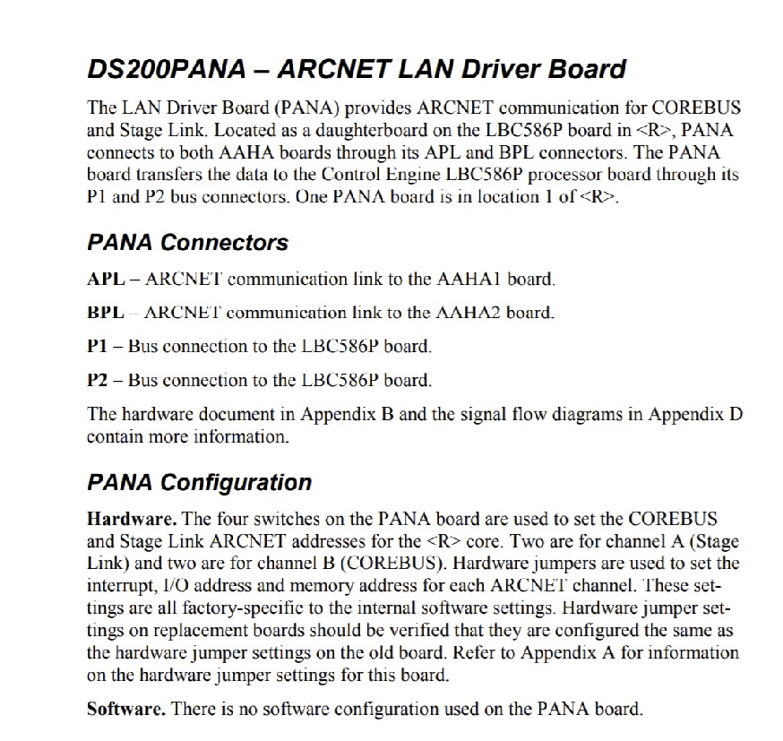
This DS200PANAH2A printed circuit board product offering exists as a member of General Electric's Mark V Turbine Control System Series, which is considered a General Electric legacy series due to its eventual manufacturing discontinuation in the years following its initial release. The Mark V Series that this DS200PANAH2A printed circuit board or PCB for short belongs to, while a General Electric legacy series, is one of the final General Electric Mark product series to make use of their patented Speedtronic control system technology. This DS200PANAH2A PCB features multiple functional descriptions, although its true functional description is that of a ARCNET LAN Driver Board, as included in this DS200PANAH2A PCB's originally-printed instructional datasheet attached above. While this DS200PANAH2A PCB is definable as an ARCNET LAN Driver Board in its own right, the originally-developed product of this functionality to exist within the Mark V is the DS200PANAH2 ARCNET LAN Driver Board missing this DS200PANAH2A PCB's A-rated functional product revision.
Hardware Tips and Specifications
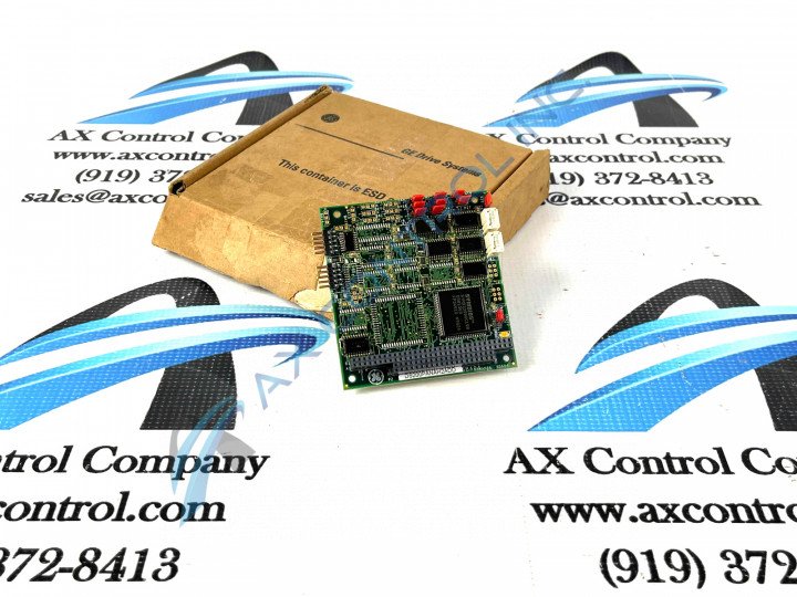
The GE ARCNET No-LAN LM Gas Turbine Control Board DS200PANAH2A features one 40-pin connector, 10 jumpers, and one 64-pin connector. The GE ARCNET No-LAN LM Gas Turbine Control Board DS200PANAH2A also has two RF FET transistors to amplify and adjust the signal. The board is 3.75 inches square in size and it has a specific location inside the Mark V Series automated drive for installation. This particular DS200PANAH2A ARCNET LAN Driver Board, while equipped with many product-specific functionality-inducing hardware components, also makes use of some of the more general, Mark V Series-standardized hardware components; including various diodes, capacitors, rectifiers, and integrated circuits in its assembly. On top of this, the DS200PANAH2A ARCNET LAN Driver Board''s base circuit board is protected by the non-standard conformal style of printed circuit board coating, which envelops and protects individual DS200PANAH2A board elements in a thin, insulated daily wear and tear protective layer. Before making a final purchase decision on this DS200PANAH2A product, it is crucial to recognize many of the connectors included for Mark V Series interfacing opportunities. Some of this DS200PANAH2A Board's available connectors include:
- The APL AHAA1 board ARCNET Communication Link
- The BPL AHAA2 board ARCNET Communication Link
- The P1 LBC586P board Bus Connection
- The P2 LBC586P board Bus Connection
This DS200PANAH2A PCB comes with a detailed installation procedure that is important to follow given its attribution as a static-sensitive product. First, remove current board from the drive before you begin the replacement. Confer with individuals familiar with the installation of the drive because they would have knowledge of the power supplies used to provide current to the drive. The power supply might have power switches however often the best practice to remove power from the power supplies is to remove the fuses. When you perform the replacement it is also best practice to not work alone. Have another servicer with you in case you need urgent help if a serious safety concern arises. The other individual can call for help or provide assistance. Use a testing device that can detect the presence of power in the drive. The tester must be calibrated to test for power in the high voltage drive and all the controls must be in the proper positions for the test. Once your are certain that the drive is free of current, examine the old board and record how the selectors for the RF FETs are set. There are two RF FETs on the board and each one has a unique identifier printed on the surface of the board.


