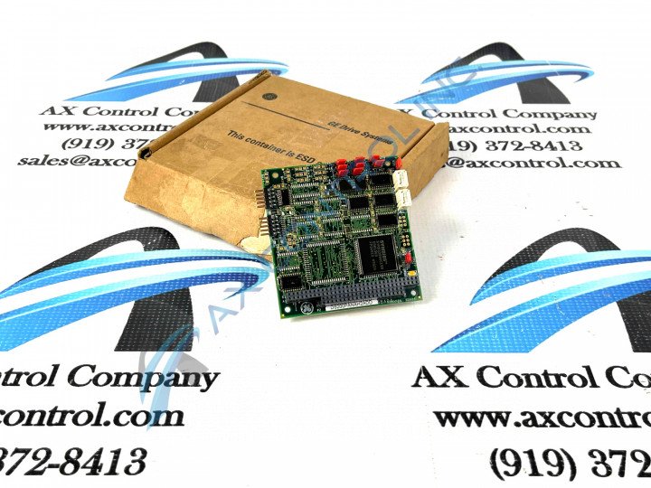
About the DS200PANAH2ADD
This DS200PANAH2ADD printed circuit board product offering was originally manufactured, as indicated above, for specific functional placement in its greater Mark V Turbine Control System Series as a ARCNET LAN Driver Board. The greater mark V Series that this DS200PANAH2ADD printed circuit board or PCB for short belongs to can be considered a now-obsolete General Electric legacy product series, as its manufacture has been discontinued due to parts obsolescence in the many years following its initial release. The DS200PANAH2ADD PCB's Mark V Series, while an obsolete legacy series, is also considered one of the final General Electric product series to make use of their patented Speedtronic control system technology first released alongside their Speedtronic Mark I Series in the late 1960s. This DS200PANAH2ADD ARCNET LAN Driver Board does not exist as the original product of its intended Mark V Series functionality; that would be the DS200PANAH2 parent printed circuit board missing this DS200PANAH2ADD PCB's full revision history including two functional product revisions and an artwork configuration revision.
Hardware Tips and Specifications
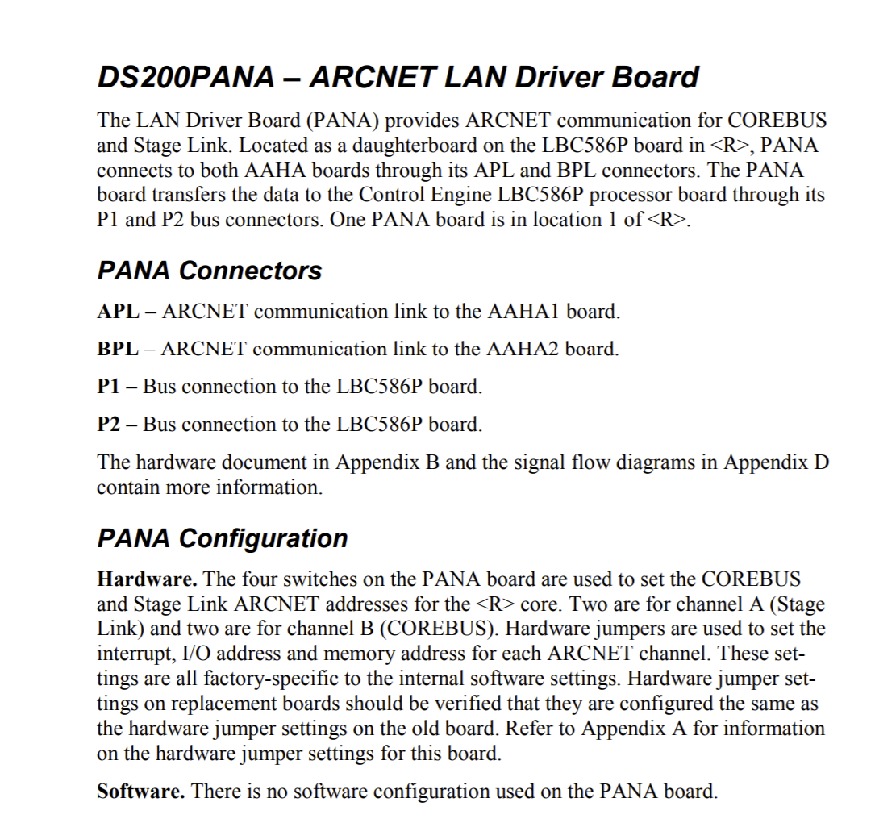
As with any Mark V Series product made available to our new and reconditioned inventory here, this DS200PANAH2ADD PCB's intended functionality is achieved through its internal assembly's adoption of a unique series of hardware components and component specifications. The GE ARCNET No-LAN LM Gas Turbine Control Board DS200PANAH2ADD features one 40-pin connector, 10 jumpers, and one 64-pin connector. The GE ARCNET No-LAN LM Gas Turbine Control Board DS200PANAH2ADD also has two RF FET semiconductors to amplify and adjust the signal. The adjustment made on the RF FETs are made by turning a small slotted knob on one side of the component. The knob has numbered indicators so you can adjust the component to a preselected adjustment. This is especially useful when you replace the DS200PANAH2ADD. This DS200PANAH2ADD printed circuit board includes a range of unique Mark V Series connectors in its external assembly on order to establish crucial interfacing with other Mark V Series products. Each of this DS200PANAH2ADD PCB's connectors is accompanied by a factory-printed nomenclature label, as listed in the DS200PANAH2ADD instructional manual attached above. Some of this DS200PANAH2ADD device's connectors include:
- The APL AAHA1 Board ARCNET Communication Link
- The BPL AAHA2 Board ARCNET Communication Link
- The P1 LBC586P Board Bus Connector
- The P2 LBC586P Board Bus Connecor
Each of the above-listed connectors in this DS200PANAH2ADD device's assembly have been named through a combination of their unique factory-printed nomenclature labels, their Mark V Series interfacing opportunities and compatible products, and finally their specific intended applications or accepted signals. Before you remove the defective DS200PANAH2ADD board note the settings of the RF FET transistor and write down the number setting. Each RF FET has a unique identifier printed on the board. For each RF FET record the identifier printed on the board and also the numbered setting for the adjustment. Inspect the jumpers on the defective board and note how they are set. First, you must wear a wrist strap that is connected on one end to a metal structure such as a support post or a leg on a desk. The other end is wrapped around the arm of the servicer. The connectors are all assigned a unique number that is printed on the board and you can use it to identify the connectors. Obtain small strips of paper and for each cable attached to the board, write down the identifier for the connector it is plugged in to. Attach the strip of paper to the cable so that you can easily know where to connect the cable on the replacement board.


