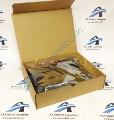
About the DS200PCCAG10ACB
As briefly hinted at in the DS200PCCAG10ACB product description above, this DS200PCCAG10ACB printed circuit board product offering was originally designed and produced for General Electric's Mark V Turbine Control System Series. The Mark V Series that this DS200PCCAG10ACB product offering belongs to, as hinted at by its extended series title, has specific applications in the control and management systems of popular and compatible wind, steam, and gas turbine automated drive assemblies. This DS200PCCAG10ACB Device's greater Mark V Series is functionally obsolete, as it exists as a legacy product series discontinued due to a manufacturer-identified functional series obsolescence. This DS200PCCAG10ACB PCB's Mark V Series, while obsolete as a legacy product series, still is something of a highly-demanded product series on the general automated industrial marketplace, as it is one of the final-produced GE Mark product series to incorporate the patented Speedtronic control system technology across a range of its product offerings. This DS200PCCAG10ACB PCB is not the originally-developed product of its specific functionality; that would be the DS200PCCAG10 parent Power Connect Board missing this DS200PCCAG10ACB PCB's three significant product revisions.
Hardware Tips and Specifications
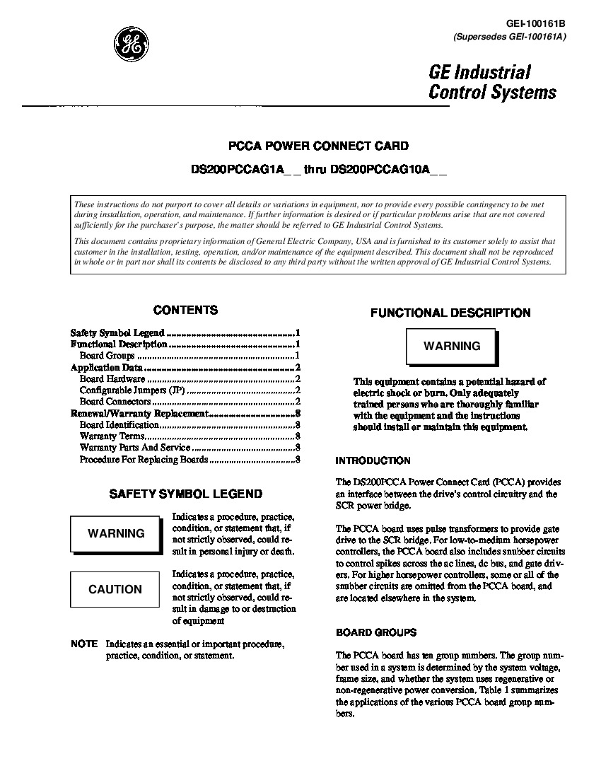
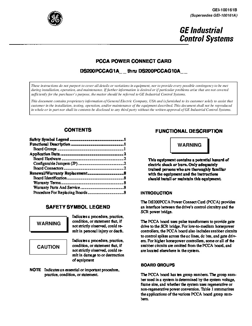
The GE DC Power Connect Board DS200PCCAG10ACB serves as an interface between the drive and the SCR power bridge. Once you install the replacement DS200PCCAG10ACB board you might have reason to download the configuration file of the drive to a laptop for review. You can edit the configuration file and change parameters to update the operation of the drive with the replacement board installed. To download the parameters file, first make sure you have a serial cable that has the matching ports you need to connect the drive to the laptop. Also, make sure the serial port on the laptop is configured properly to communicate with the drive. Use the commands on the control panel to initiate the download and when complete a message displays on the display panel that the download is complete. You can use the laptop to check the operation of the replacement board by viewing the diagnostic file. You can also access the editing software on the laptop to alter the board's parameters. When you have completed the updates, upload the file back to the drive. Use the control panel to start the download procedure and when the operation is complete, a will be message displayed.
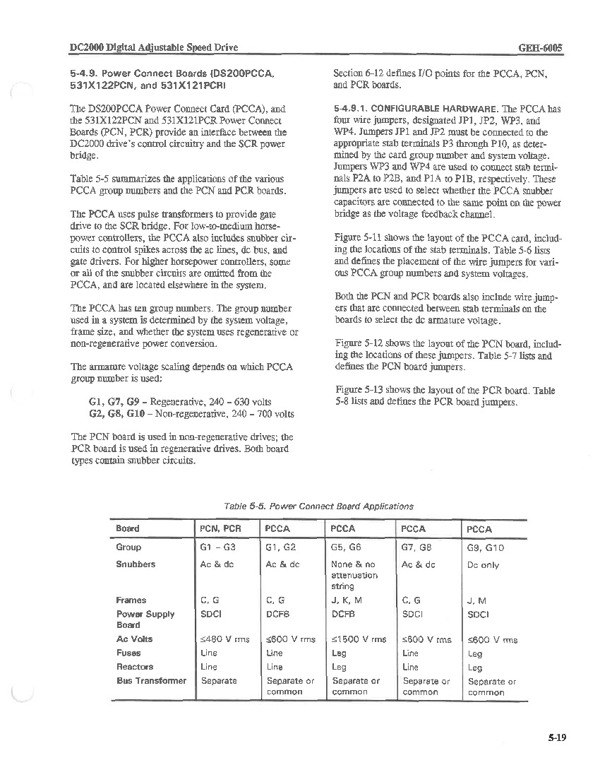
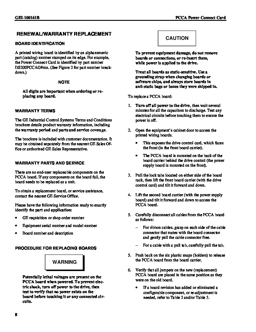
To replace the DS200PCCAG10ACB board, you must disconnect all power to the drive. To do that, access the 3-phase power supplies that provide current to the drive. Then, remove the fuses from the power supplies. Next, you can open the bay that contains the boards and remove the wires and connectors. This DS200PCCAG10ACB printed circuit board, as indicated in the DS200PCCAG10ACB instructional manuals and datasheets provided above, has specific applications in the DC2000 Mark V Subseries' automated drive assembly. Given this DS200PCCAG10ACB product offering's unique group ten Mark V Series product grouping, it is only considered to possess Dc styles of snubbers, unlike any other Mark V Series product grouping. In addition to this, this DS200PCCAG10ACB PCB's group ten grouping delegates its J and M-style frames compatibility, its SDCI power supply board usage, its leg styles of both fuses and reactors, and finally its maximum ac voltage of 600 V rms. Eight total connectors are included in this DS200PCCAG10ACB PCB's assembly specifically for establishing a connection to the Mark V Series' DCFB Board; each of these is accompanied by their own factory-printed nomenclature label. This DS200PCCAG10ACB PCB's DCFB connectors include:
- The 5PL-1 A6F-labeled Drive cell 6F gate-pulse transformer connector
- The 5PL-2 P24-labeled +24 volt output connector
- The 5PL-3 A5F-labeled Drives cell 5F gate-pulse transformer connector
- The 5PL-4 P24-labeled +24 volt output connector
- The 5PL-5 A4F-labeled Drives cell 4F gate-pulse transformer connector
- The 5PL-6 P24-labeled +24 volt output connector
- The 5PL-7 A3F-labeled Drives cell 3F gate-pulse transformer connector
- The 5PL-8 P24-labeled +24 volt output connector


