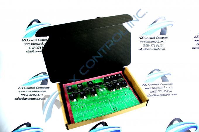
About the DS200PCCAG5A
The GE DC Power Connect Board DS200PCCAG5A serves as an interface between the drive and the SCR power bridge within the greater Mark V Series automated drive assembly in which it was manufactured for by General Electric. General Electric's Mark V Series has specific applications in the control and management systems of wind, steam and gas turbine automated drive assemblies specifically, as you could probably tell from its extended name. The DS200PCCAG5A Power Connect Boards' Mark V Series is considered a General Electric legacy series, as it has been discontinued for production in the years following its initial release. While considered a GE legacy series, the DS200PCCAG5A Power Connect Board's greater Mark V Turbine Control System Series is one of the most recent General Electric product lines to feature the patented Speedtronic control system technology in its various products, including this DS200PCCAG5A PCB. This DS200PCCAG5A Power Connect Board is not considered the original product with its exact functionality manufactured for GE's Mark V Turbine Control System Series; that would be the DS200PCCAG5 Power Connect Board missing this DS200PCCAG5A product's A-rated functional product revision.
Hardware Tips and Specifications
This DS200PCCAG5A printed circuit board product offering adopts a necessary series of hardware component inclusions and specifications to reach its intended Mark V Series functionality as a Power Connect Card or Power Connect Board. For starters, the internal assembly of this General Electric product offering is chock full of various Mark V Series-standardized voltage-limiting hardware components, including numerous resistors, capacitors, and diodes, as well as integrated circuits.
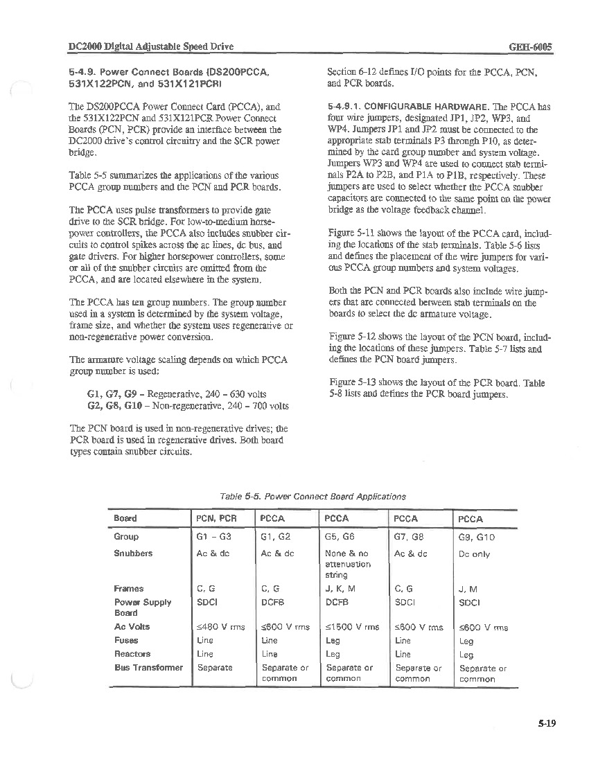
This DS200PCCAG5A Power Connect Card is attributable to the fifth grouping of Mark V Series product offerings, which pertains to several relevant hardware specifications. This DS200PCCAG5A Power Connect Card's group 5 Mark V Series grouping details it as a Mark V Series printed circuit board with no ac or dc snubbers in its assembly, with no attenuation string present either. Due to this series grouping, the DS200PCCAG5A PCB is also considered compatible with J, K and M-style Mark V Series frames and the DCFB Power Supply Board, which is also available for repair and replacement right here through AX Control. Finally, this DS200PCCAG5A product's Group 5 attribution additionally exposes its status as a PCB with leg fuses and reactors that has separate or common style of bus transformers and a maximum ac voltage of up to 1500 v rms. Much like the attributes garnered by this DS200PCCAG5A PCB's group five series grouping, this DS200PCCAG5A PCB's various manually-moveable jumpers and their functions are described in detail in the original General Electric instructional manual attached above for your convenience. Before making an ultimate purchase decision for this DS200PCCAG5A product offering, it is important to realize that its originally-introduced performance specifications and dimensions have surely been altered through its inclusion of an A-rated functional product revision in its assembly.
The DS200PCCAG5A board has several cables connected to it, depending on the installation and the requirements of the site. It is always important to remove the cables from the old board and install them on the new replacement board; however, care must be taken to not damage the cables and depending on the type of cable, different procedures must be followed. Ribbon cables are common to find in the drive for carrying signals for transmitting and receiving information. Ribbon cables are delicate and need to be treated carefully to avoid damage. To remove a ribbon cable from this DS200PCCAG5A board's assembly, do not pull the cable out from the ribbon portion the cable. With one hand, hold the connector on the board. With the other hand, hold the connector on the cable. Pull the cable out without touching the ribbon. Some cables in this DS200PCCAG5A Power Connect Card's assembly are held in place on the board with a tab that secures the cable to the connector. Use a finger to pull the tab; this releases the cable from the connector. At the same time, you should be able to pull the cable free from the board.


