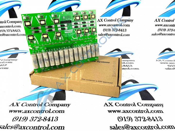
About the DS200PCCAG7A
This DS200PCCAG7A printed circuit board was originally designed and produced to exist as a member of General Electric's Mark V Turbine Control System Series, as specified above and in original General Electric instructional manual materials. As specified by its name, the Mark V Series has specific intended applications in the control and management systems of compatible gas, steam, and wind turbines, within their automated drive assemblies. The Mark V Turbine Control System Series that this DS200PCCAG7A printed circuit board or PCB for short belongs to has to be considered a legacy series, as its manufacturing has been essentially discontinued in the years following its initial release. This PCCA-abbreviated printed circuit board's Mark V Series, while considered a legacy series, is also one of the final General Electric product series to make use of their patented Speedtronic technology in its products. While generally definable as a General Electric printed circuit board product offering, this DS200PCCAG7A PCB has a more specifically-defined functional role as a Power Connect Card or Power Connect Card Assembly, based on these descriptions' insertions in relevant Mark V Turbine Control System Series instructional manual materials. While this DS200PCCAG7A PCB is definable as a Power Connect Card, the original Power Connect Card to exist as a member of the Mark V Series its its parent product; the DS200PCCAG7 PCB missing this DS200PCCAG7A board's singular A-rated functional product revision.
Hardware Tips and Specifications
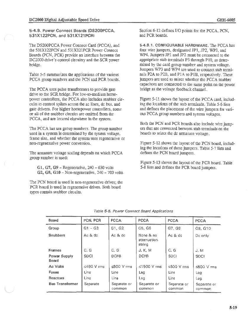
The GE DC Power Connect Board DS200PCCAG7A serves as an interface between the drive and the SCR power bridge, and necessitates its own set of hardware inclusions and specifications given its specific functionality. The DS200PCCAG7A board doesn’t have any servicable parts and cannot be repaired so if it is determined that the board is defective the only option is to replace it. With this in mind, it is probably a massive benefit that this DS200PCCAG7A Power Connect Card makes use of General Electric's normal style of PCB coating in its assembly, which should exist as a thick layer of PCB protective coating and insulation that extends to individual hardware elements on this DS200PCCAG7A product's base board on a functional priority basis. This DS200PCCAG7A PCB makes use of several additional protective hardware elements in its assembly, making use of the standard number of diodes, capacitors, and integrated circuits present with any mark V Series product offering. Additionally, both ac and dc styles of snubbers have been adopted into this PCCA-abbreviated product's normal Mark V Series assembly. This was discovered upon an analysis of this DS200PCCAG7A product's group seven Mark V Series grouping, which is seen as the identifying factor behind this DS200PCCAG7A PCB's acceptance of C and G-style frames, its correspondence with the SDCI Power Supply Board, its maximum ac voltage of up to 600 r ms, its acceptance of line styles of both fuses and reactors, and finally its need for either a separate or common bus transformer.
Several important manually-moveable hardware jumpers have additionally been applied to the assembly of this DS200PCCAG7A product, for the selection of different and important processing values, as determined in this DS200PCCAG7A Power Connect Board's original instructional manual inserted above. This Mark V Turbine Control System Series group seven product offering has an armature voltage scaling of 240 to 630 volts of non-regenerative voltage, as typical with PCCA Power Connect Boards credited to this seventh grouping. Before making a final purchase decision on this DS200PCCAG7A Power Connect Board, it is crucial to consider the fact that its A-rated functional product revision almost certainly alters its originally-introduced performance specifications and dimensions, which truly correspond to the DS200PCCAG7 parent Power Connect Card mentioned in the original DS200PCCAG7A instructional manual. This DS200PCCAG7A printed circuit board has been drilled in several locations around the outside of its base circuit board for installation purposes, with each factory-drilled hole being voltage-secured by a ringlet of insulated material, in observance of potentially-present damaging surface voltages and static electricity.


