About the DS200PCCAG7ACB
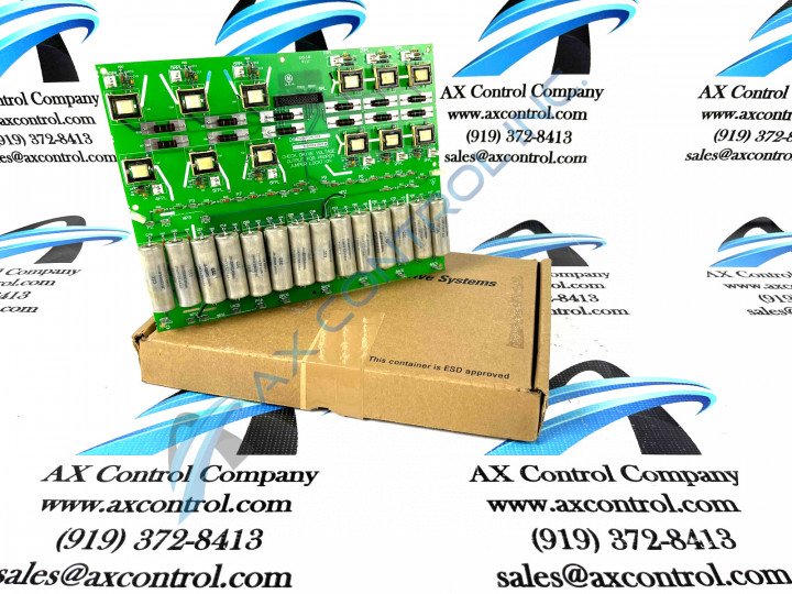
The GE Industrial Control Systems DC2000 series DC Power Connect Board DS200PCCAG7ACB serves as a crucial interface between the greater DC200 drive and the SCR power bridge. It's important to note that the DS200PCCAG7ACB board is not repairable and does not contain serviceable parts. If the board exhibits unexpected behavior, it should be replaced entirely.
Hardware Tips and Specifications
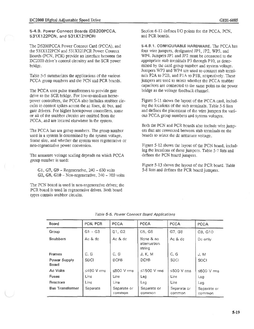
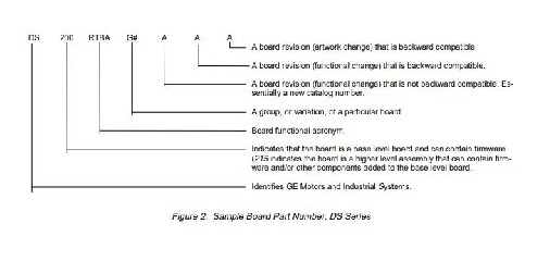
The PCCA possesses a total of ten potential group numbers, and the specific group number employed within a system is determined by factors such as the system voltage, frame size, and whether the system utilizes regenerative or non-regenerative power conversion methods. This specific DS200PCCAG7ACB model is a member of the seventh group, as designated by the "G7" portion present in its product number. As outlined in its corresponding GE Instructional Manual above; the DS200PCCAG7ACB's Group seven status lends itself to a number of unique product specifications, including:
- both ac and dc type snubbers
- a C or G style of frame
- power supply board SDCI compatibility
- <600 V rms AC volts
- line fuses and reactors
- separate or common bus transformer compatibility
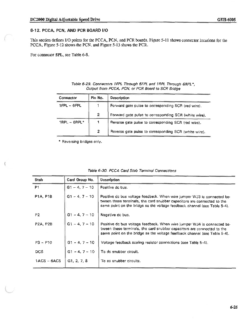
Beyond the easily-distinguishable specifications revealed through this product's group number designation, a wealth of additional information is available for the DS200PCCAG7ACB through a careful analysis of its instructional manual. This is a customizable model of DC2000 series product; featuring an elevated number of adjustable hardware jumpers. In total, the DS200PCCAG7ACB, abbreviated commonly as PCCA, has four adjustable hardware jumpers available affixed to its base plate. As with many of the components on the face of this PCB, this PCCA board's four adjustable jumpers are specifically labeled. The first two of these jumpers are connected to appropriate stab terminals in locations P3 to P10, and are labelled as JP1 and JP2. The final two customizable hardware jumpers on the DS200PCCAG7ACB are WP3 and WP4, and are used in order to conjoin P2A to P2B, and P1A to P1B, respectively. Voltage protection for this PCCA component board are handled by a series of present snubber circuits, as well as multiple pulse transformers.
Installation Tips and Specifications
A number of important specifications are crucial to the proper and safe installation of this PCCA module. When replacing the DS200PCCAG7ACB board, it is recommended to utilize the downtime for drive replacement to perform periodic maintenance as well. This ensures that the drive remains in optimal working condition and avoids the need for separate maintenance scheduling.
The drive is designed for generally minimal maintenance and has a long service life. During the power-off state, which is needed for any attempt at safe module installation; it is advisable to inspect the motor for any dust or debris accumulation. Clean the motor and all components using a mild cleaner and a cleaning cloth, avoiding harsh cleaners that may damage terminals, connectors, and solder points.
Additionally, it is crucial to check the tightness of all wires and cables, ensuring secure connections. Inspect cables for signs of fraying, wear, and worn insulation, tightening any loose cables as needed. Follow the torque tightening guidelines provided and ensure that cables meet the specified torque tightening specifications, which can be found on a label on the drive.


