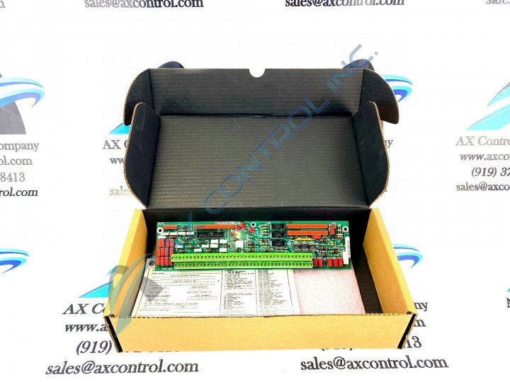
About the DS200PTBAG1A
This DS200PTBAG1A printed circuit board product offering from General Electric was originally designed and produced specifically for placement in the Mark V Turbine Control System Series, as revealed through our product description provided above. The Mark V Series that this DS200PTBAG1A device belongs to is something of a self-explanatory GE Mark product series, as it exists with specific intended applications in the management and control systems of General Electric-compatible steam and gas turbine automated assemblies. The Mark V Series that this DS200PTBAG1A device belongs to has to be considered a now-obsolete legacy product series as a whole however, given the eventual manufacturing discontinuation that was necessitated due to a General Electric-identified functional full-series obsolescence in one of the many years following this DS200PTBAG1A device's first inception. Because of this, the Mark V Series is much more limited in its range than later GE Mark Series Suite iterations, which extend to possible alternative energy settings as well. This DS200PTBAG1A device is still desirable on the greater general market given its status as a product within one of the final GE Mark product series to make use of the esteemed and GE-patented Speedtronic control system technology.
Hardware Tips and Specifications
The GE Termination Board DS200PTBAG1A features 2 terminal blocks with terminals for 72 signal wires in each. It also contains 3 10-pin connectors. The IDs for the 10-pin connectors are JJR, JJT, and JJS. It also contains terminal posts for 6 signal wires. In terms of its dimensions, The GE Termination Board DS200PTBAG1A is 3 inches in height and 11.5 inches wide and it features 1 hole in each corner for attaching the board to the board rack inside the drive. Because of the numerous signal wires and ribbon cables that attach to the board, it is best practice to map out where the signal wires attach on the board and have a plan to attach the wires to the same connectors on the replacement board. If you fail to attach the signal wires to the same terminals, the drive downtime will increase while the signal wires are attached to the correct terminals, which would in hand inconvenience operations at the site and reduce productivity. To prevent that from happening, examine the old board on the drive while all the signal and ribbon cables are still attached. Mark on the signal wires where they are attached using the terminal ID. The ID of 1 terminal block is TB1 and the other is TB2. To ID a specific terminal, use the numerical ID of the terminal. For example, TB1 27 is the terminal 27 on the TB1 terminal block. TB2 70 is the terminal 70 on the TB2 terminal block. You might find it helpful to create tags on which to mark the ID.
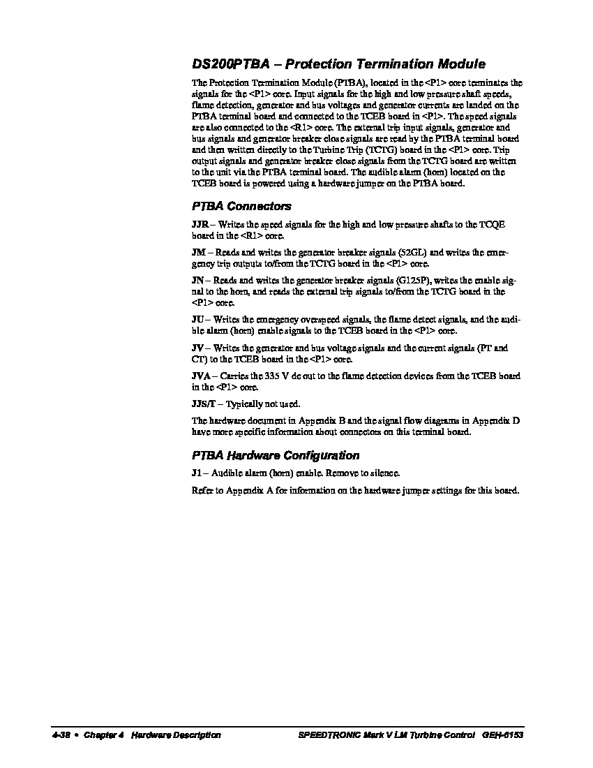
This DS200PTBAG1A Protection Termination Board makes use of a few pieces of customizable hardware in its assembly, the most obvious of those being its manually-moveable hardware jumper. This jumper has been included in the assembly of this DS200PTBAG1A Protection Termination Module as it controls the audible alarm or horn that comes standard with this General Electric product offering. To silence the horn included in the assembly of this PTBA-abbreviated Termination Module, the DS200PTBAG1A Board administrator must remove the aforementioned hardware jumper completely. This DS200PTBAG1A Protection Termination Board plays a crucial role in the normative functionality of related Mark V Series Boards TCEB and TCTG, both of which are also available for repair or replacement here at AX Control. This DS200PTBAG1A Protection Termination Module should be relatively well-protected beneath its standard layer of normal-style printed circuit board coating, which is a basic protection against daily wear and tear.


