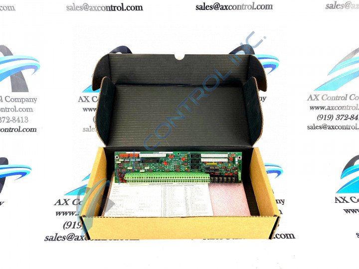
About the DS200PTBAG1B
This DS200PTBAG1B General Electric printed circuit board product offering was originally manufactured for use specifically in the Mark V Turbine Control System Series. As you could probably tell from its full name, the Mark V Series is a series of General Electric printed circuit boards and other automated drive assembly components that have specific applications in the management and control systems of wind, steam, and gas turbines. The Mark V Series is a legacy series as it is no longer in active production by its original manufacturer, but is also one of the final General Electric Mark Series released featuring products utilizing the patented Speedtronic control system technology. This DS200PTBAG1B Mark V Turbine Control System Series printed circuit board product offering is better-definable as a Protection Termination Module; the original functional description this DS200PTBAG1B board receives in Mark V Series and General Electric instructional documentation. While this DS200PTBAG1B printed circuit board is certainly definable as a Protection Termination Module, it does not exist as the original product of this functionality within the Mark V Series; that would be the DS200PTBAG1 parent Protection Termination Module notably missing this DS200PTBAG1B product's B-rated functional product revision.
Hardware Tips and Specifications
As with any General Electric printed circuit board product offering, this DS200PTBAG1B PCB makes use of its own set of functionality-encouraging hardware components and component specifications. The GE Termination Board DS200PTBAG1B features 2 terminal blocks with terminals for 72 signal wires in each. It also contains 3 10-pin connectors. The IDs for the 10-pin connectors are JJR, JJT, and JJS. It also contains terminal posts for 6 signal wires. The GE Termination Board DS200PTBAG1B is designed to process 7 separate termination signals. The signals present in this DS200PTBAG1B Board's assembly are overspeed magnetic pickups, flame detectors, bus volts, generator volts and current, synchronizing, protective inputs, and alarm horn enable and disable hardware jumper location signals. A series of connectors are identified for this DS200PTBAG1B product offering in its original instructional manuals. These connectors include:
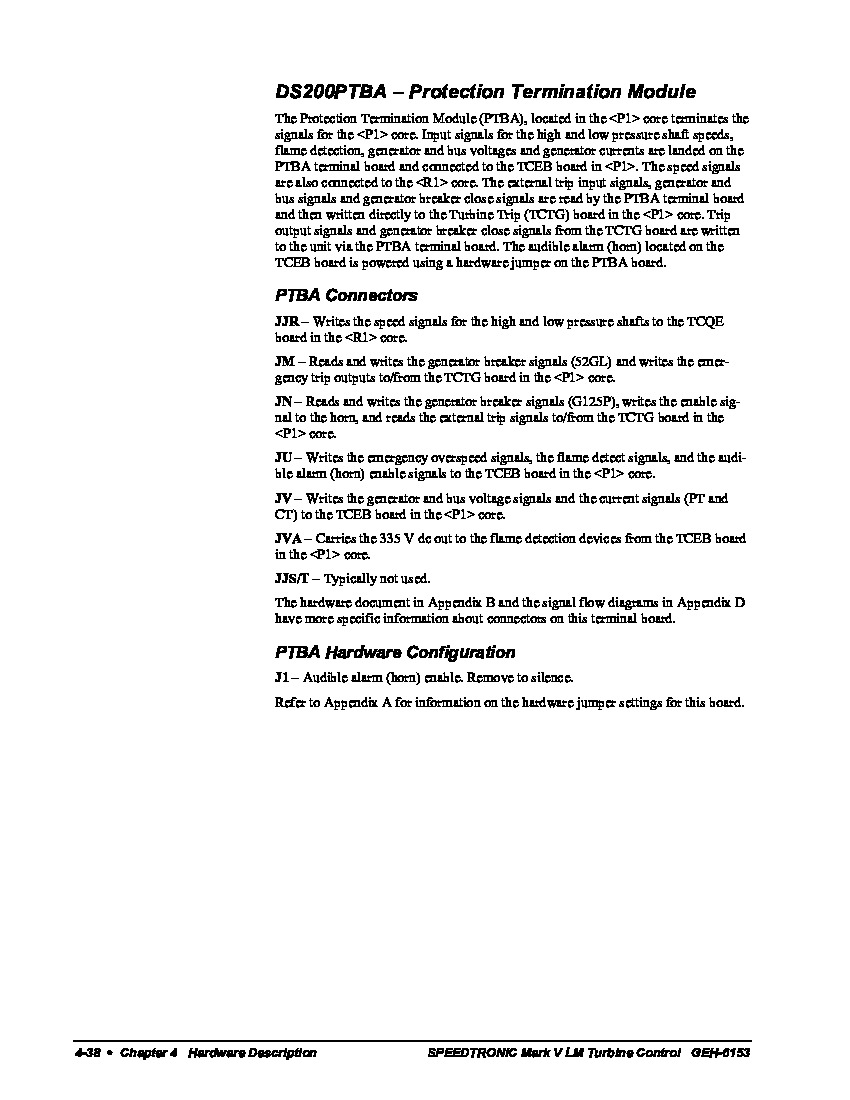
- The JJR TCQE Board High and Low Pressure Shaft Speed Signal Connector
- The JM TCTG Board Generator Breaker Emergency Outputs Signal Connector
- The JN TCTG Board Generator Breaker External Trip Signal Connector
- The JU TCEB Board Various Diagnostic Signals Connector
- The JV TCEB Board Generator and Bus Breaker Signals Connector
- The JVA TCEB Board Flame Detection Signals Connector
- The JJS/T Connector
All of the aforementioned connector types available to the assembly of this DS200PTBAG1B Protection Termination Module have been named through a combination of their factory-printed nomenclature labels, Mark V Series interfacing potentials, and specific function to the DS200PTBAG1B Protection Termination Module and greater Mark V Series automated drive assembly except for the JJS/T Connector; which hasn't been named as it exists as a vestigial structure that typically goes unused during normative functionality of this DS200PTBAG1B Module. All of the connections made to the base circuit board of the DS200PTBAG1B Protection Termination Module should receive some basis of protection from the normal style of thick rudimentary PCB coating applied to the base circuit board of this DS200PTBAG1B product.
General Electric details many safe and crucial installation procedures for this DS200PTBAG1B PCB. To remove a signal wire from a terminal on a terminal block, have on hand a narrow flat-blade screwdriver. This procedure should only take place when power is removed from the drive. Use a tester to detect the presence of power in the drive after power is removed. This is because components in the drive, like capacitors, store power during normal drive operations. So, even when you remove the source of power, current might still be present. If you wait 30 seconds, the power in the components exits the drive. However, to avoid shock, use a tester before you touch any components in the drive. Locate the signal wire you want to remove using the terminal block ID and the terminal numerical ID, before using a narrow screwdriver to loosen the terminal retention screw and pull the signal wire from the terminal. Use tape or other means to mark on the signal wire the ID of the terminal it is connected to. To connect the signal wire, insert it into the terminal and tighten the terminal retention screw.


