About the DS200PTCTG1A
This DS200PTCTG1A printed circuit board product offering from General Electric, as specified in very loosely-available instructional manual materials online, is a Potential Transformer Current Transformer Board originally manufactured specifically for the Mark V Turbine Control System Series. The Mark V Series that this DS200PTCTG1A printed circuit board or PCB for short belongs to, as defined in its full extended series name, has a selection of specific applications in the control and management systems of popular and compatible wind, steam, and gas turbine automated drive assemblies. With this being the case, this DS200PTCTG1A product's greater Mark V Series must still be considered obsolete overall, as it is definable as a General Electric legacy Mark product series whose manufacture was discontinued due to a retailer-introduced functional series obsolescence in one of the many many years past its original General Electric product series rollout. This DS200PTCTG1A device's Mark V Turbine Control System Series, while obsolete as a whole, is still able to attract something of a consistent cult demand on the general automated industrial marketplace, as it exists as one of the lastly-developed GE Mark product series to incorporate the patented Speedtronic control system technology across a range of its different offerings including this DS200PTCTG1A PCB.
Hardware Tips and Specifications
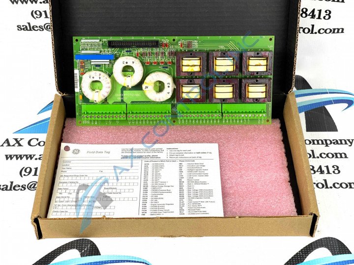
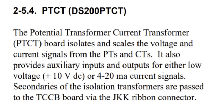
The DS200PTCTG1A Potential Transformer Current Transformer Board uses the abbreviation of PTCT in GE documentation and provides current signals from the PTs and CTS in an EX2000 Excitation Control System. The General Electric Potential Transformer Current Transformer board DS200PTCTG1A features 1 terminal block with terminals for 72 signal wires in each. It also contains 1 50-pin connector. The IDs for the terminals on the terminal block include OUT2, OUT1, COM1, COM2, P15, SO21, and L23. It also contains terminal posts for 6 signal wires. Generally, this DS200PTCTG1A device's voltage suppression and limitation strategy involves its normal Mark V Series assembly's incorporation of a series-standardized selection of voltage-limiting hardware components including various different styles of capacitors, resistors, diodes, rectifiers, and finally specialized integrated circuits. This DS200PTCTG1A printed circuit board is actually not the originally-printed device of its specific Mark V Series functionality; that would actually be the DS200PTCTG1 parent Potential Transformer Current Transformer not making use of this DS200PTCTG1A device's singular A-rated functional product revision. This DS200PTCTG1A PCB's functional product number reveals many other hardware details in a series of consecutive functional naming elements. For example, the DS200PTCTG1A functional product number is started by the dual-functional DS200 series tag delegating this DS200PTCTG1A device's normal Mark V Series assembly and domestic location of original manufacture. Some of the other pertinent hardware information revealed through the DS200PTCTG1A functional product number include this PCB's:
- PTCT functional product abbreviation
- Normal PCB coating style
- Group one Mark V Series product grouping
- A-rated primary functional product revision
The GE Signal Conditioner Board DS200PTCTG1A is also populated with 6 jumpers. The IDs for the jumpers are suffixed with BJ followed by a numerical value. For example, one jumper ID is BJ3 and another jumper ID is BJ5. When the board is first configured for use in the drive, refer to the documentation that came with the board because it contains the information about the purpose of each jumper and how it can configure the board. Some of the jumpers remain in the default position. The default is the position at which the jumpers come from the factory. It is the typical configuration used by most installations. Also available is the configuration provided by the alternate position. The 3-pin jumpers have 2 positions. One is when the jumper covers pin 1 and pin 2. The other position is when the jumper covers pins 2 and 3. Depending on which two pins are covered, the jumper creates a contact between the two pins. Some jumpers have only one supported position and the jumpers comes with that position as the default position. The alternate position is intended for factory use only. That position is used for testing during manufacturing.


