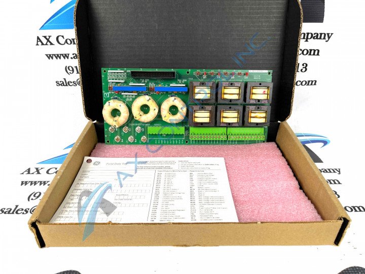
About the DS200PTCTG1B
This DS200PTCTG1B printed circuit board has something of an earful of a functional product description, being introduced as a Potential Transformer Current Transformer in original General Electric instructional manual materials. With that being said, this DS200PTCTG1B printed circuit board or PCB for short is not too much of a sophisticated Mark V Series product offering, as it still features a normal assembly as signified by the presence of the DS200 series tag in the DS200PTCTG1B functional product number. This DS200PTCTG1B printed circuit board is not the original Potential Transformer Current Transformer that was manufactured for the Mark V Series; that would be the DS200PTCTG1 parent printed circuit board missing this DS200PTCTG1 product's singular B-rated functional product revision.
Hardware Tips and Specifications
The General Electric Signal Conditioner Board DS200PTCTG1B features 1 terminal block with terminals for 72 signal wires. It also contains 1 50-pin connector. The IDs for the terminals on the terminal block include OUT2, OUT1, COM1, COM2, P15, SO21, and L23. This Mark V Series product offering also contains terminal posts for 6 signal wires. This is about the extent of hardware component and specification information available upon a visual inspection of the DS200PTCTG1B PCB alone. The DS200PTCTG1B functional product number is a good source of other specificatory information, including:
- The DS200PTCTG1B PCB's normal assembly style and domestic manufacture
- The DS200PTCTG1B PCB's PTCT functional acronym
- The DS200PTCTG1B PCB's normal PCB coating and Group One Mark V Series grouping
- The DS200PTCTG1B PCB's singular B-rated functional product revision
The GE Signal Conditioner Board DS200PTCTG1B also is populated with test points that provide the means for a qualified individual to test the function of the various circuits on the board. To use the test points, the board must be removed from the drive and placed on a level clean surface and the board must also rest on a static protective surface. For example, a workbench or a desk is an appropriate work area. A wrist strap is mandatory equipment to have on hand during the totality of this process. The test points have IDs assigned to them, as with any other individual hardware component in this DS200PTCTG1B Board's assembly. The IDs are prefixed with TP followed by a number. Some of the IDs for the test points are TP1, TP5, and TP20.


