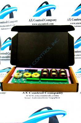
About the DS200PTCTG2B
This DS200PTCTG2B General Electric printed circuit board product offering was originally designed and produced to exist within their Mark V Turbine Control System Series. As you can probably tell by its name, the Mark V Series has specific and crucial applications in the control and management systems of compatible steam, wind, and gas turbine automated drive assemblies, and is considered a General Electric legacy series due to its eventual discontinuation by the original manufacturer. While this DS200PTCTG2B product's Mark V Turbine Control System Series is a legacy GE series, it also exists as one of the final GE Mark product series to make use of the patented Speedtronic control system technology. This DS200PTCTG2B printed circuit board or PCB for short is better-definable by its official functional product description as a Potential Transformer Current Transformer, although some fringe General Electric instructional documentation refers to it simply as a Signal Conditioner Board. This DS200PTCTG2B printed circuit board product offering is not the original Mark V Turbine Control System Series product of its functionality; that would be the DS200PTCTG2 Potential Transformer Current Transformer missing this DS200PTCTG2B product's B-rated functional product revision.
Hardware Tips and Specifications
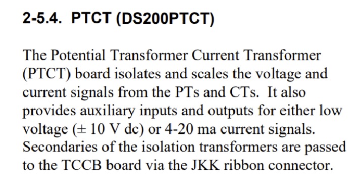
This DS200PTCTG2B Potential Transformer Current Transformer makes use of its own particular set of functionality-introducing hardware component inclusions and specifications. The GE Signal Conditioner Board DS200PTCTG2B features 1 terminal block with terminals for 72 signal wires. It also contains 1 50-pin connector. The IDs for the terminals on the terminal block include OUT2, OUT1, COM1, COM2, P15, SO21, and L23. It also contains terminal posts for 6 signal wires. The normal Mark V Series assembly of this DS200PTCTG2B Potential Transformer Current Transformer is additionally populated by a series of Mark V Series-standardized voltage-limiting hardware components. Some of these components included various resistors, capacitors, and integrated circuits, as well as this DS200PTCTG2B printed circuit board's normal style of PCB coating; which exists as a thick rudimentary layer of DS200PTCTG2B daily wear and tear protection that envelops and protects individual DS200PTCTG2B board hardware elements on a functional priority basis. The JKK ribbon connector in this DS200PTCTG2B Mark V Turbine Control System Series product offering's normal style of Mark Series assembly play a crucial role for its greater Mark V Series automated drive assembly; passing the secondaries of isolation transformers to the TCCB Board. This TCCB board is additionally available for repair or replacement in our inventory of General Electric products. Before making any ultimate purchase decision on this DS200PTCTG2B product offering, it is important to keep in mind that it has been edited from its original performance specifications and dimensions through its inclusion of a B-rated functional product revision.
The GE Signal Conditioner Board DS200PTCTG2B, when it is installed in the drive has the potential to have multiple signal wires and ribbon cables attached to it. Some of the signal wires transmit signals from the board to other boards in the drive for processing. Other signal wires transmit signals to the board for processing. The signals are then sent to other boards for further processing. Due to the many wires, it is important to consider that air must flow freely inside the drive and that the cables must be routed so that they do not block the air flow. When the drive is in operation, cool air enters the drive from the bottom and flows around, over, and under the heat-generating components. These components include the processing boards that send and receive signals. It also includes the motor and the associated moving parts. If the air in the Mark V Series automated drive assembly is trapped by bundles of DS200PTCTG2B board wires, the interior of the drive might get too hot, which would cause an over-temperature condition and would cause the drive to shut down automatically. To prevent an over temperature condition, keep the wires in the DS200PTCTG2B Potential Transformer Current Transformer's assembly away from the air vents and rout the cables along the sides of the drive interior.


