About the DS200QTBAG1A
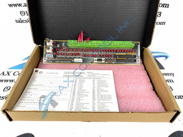
This DS200QTBAG1A printed circuit board was originally manufactured, as alluded to above, by General Electric, specifically for placement in their Mark V Turbine Control System Series. The Mark V Series that this DS200QTBAG1A product offering belongs to is considered a legacy product series, as it is obsolete given an eventual manufacturing discontinuation in the many years following its initial release. While the Mark V Series that this DS200QTBAG1A Board belongs to is considered now-obsolete due to its legacy status, it is something of a recent product series offering, as it exists as one of the final General Electric product series to incorporate the trusted automation brand's patented Speedtronic control system technology into its various iterations and revision versions of its product offerings. This DS200QTBAG1A printed circuit board is definable functionally as an RST Termination Board or simply as a Termination Module, based on both of these functional descriptions' insertions in relevant GE Mark V Turbine Control Systems Series instructional manual materials. While this is true, this specific DS200QTBAG1A product offering is not the original device of its Mark V Series functional role; that would be the DS200QTBAG1 parent Termination Module not making use of this DS200QTBAG1A product's singular A-rated functional product revision.
Hardware Tips and Specifications
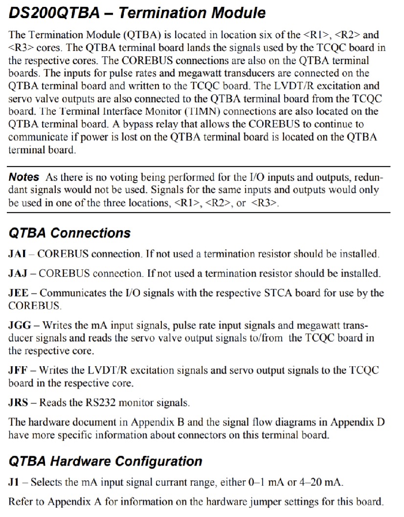
The GE RST Termination Board DS200QTBAG1A features 2 terminal blocks with terminals for 72 signal wires in each. It also contains 1 40-pin connector. The ID for the 40-pin connectors is JFF. It also is populated with 1 serial connector. The GE Termination Board DS200QTBAG1A is also populated with 1 34-pin connector. The ID for the 34-pin connector is JGG. Each of the specific connectors in the assembly of this DS200QTBAG1A Mark V Series product offering is listed in the DS200QTBAG1A instructional manual material inserted in the manuals tab above for your convenience. This DS200QTBAG1A instructional manual describes the specific applications of each DS200QTBAG1A connector as follows:
- The JAI COREBUS Connector
- The JAJ COREBUS Connector
- The JEE STCA Board I/O Signals Connector
- The JGG TCQC Board Various Signals Connector
- The JFF LVDT/R and Servo Output Signals Connector
- The JRS RS-232 Monitor Signals Connector
Each of these previously-listed connectors in the assembly of this DS200QTBAG1A product offering have been named through a combination of their factory-printed nomenclature labels, their Mark V Series interfacing potentials and compatible products, and finally their specific application in terms of the DS200QTBAG1A Board itself. The 2 terminal blocks support a total of 144 terminal signal wires. Each of the terminals connects to a specific signal wire for processing. When the factory-new board is delivered to your site, it contains information about the 144 terminals and provides specific information about the purpose of each terminal. Use that information to know where to connect the signal wires. The ID of one terminal block is TB1 and the ID of the other terminal block is TB2. Additionally, each terminal is assigned a number. To ID a particular terminal, first identify the terminal block, then identify the terminal number. For example, TB1-66 is the terminal 66 on terminal block TB1. TB2-33 is the terminal 33 on terminal block TB2.
Once the signal wires are connected properly and the board is operating as required, there is no need to disconnect or connect the signal wires from the terminals, unless there is a reason to change the processing of the board. This might be the case if the task assigned to the drive changes or other conditions change. Before you replace the board, mark on the signal wire the terminal block ID and the terminal number.


