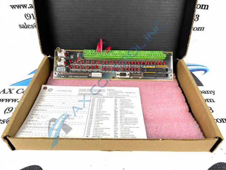
About the DS200QTBAG1ADC
This DS200QTBAG1ADC RST Termination Board was originally manufactured by the trusted automated industrial giant General Electric, specifically for placement in their now-defunct Mark V Speedtronic product series. The Mark V Series, as you can probably tell by its full extended series name, has specific applications in the control and management systems of established GE-compatible turbines, and is considered a now-obsolete legacy product series due to its eventual manufacturing discontinuation in the years following its initial release. This DS200QTBAG1ADC printed circuit board or PCB for short's greater Mark V Series is also one of the final product series to make use of General Electric's patented Speedtronic control system technology first introduced alongside the rollout of the Mark I in the late 1960s. While this DS200QTBAG1ADC product offering is definable as an RST Termination Board in its own right, the original product of this functional role developed for the Mark V Series is the DS200QTBAG1 parent RST Termination Board notably missing all of this DS200QTBAG1ADC product's three significant product revisions.
Hardware Tips and Specifications
As with any General Electric Mark V Series product offering, this DS200QTBAG1ADC PCB's specific functionality is developed through its internal assembly's adoption of a particular series of functionality-introducing hardware components and component specifications. The GE RST Termination Board DS200QTBAG1ADC features 2 terminal blocks with terminals for 72 signal wires in each. It also contains 1 40-pin connector. The ID for the 40-pin connector is JFF. It also is populated with 1 serial connector. The GE RST Termination Board DS200QTBAG1ADC picks up various signals from the control system and facilitates connection to fuel flow signals. Some specifications for the DS200QTBAG1ADC are as follow:
- 6 magnetic pulse rate inputs
- 8 servo value outputs
- 6 excitation sources for LVDTs
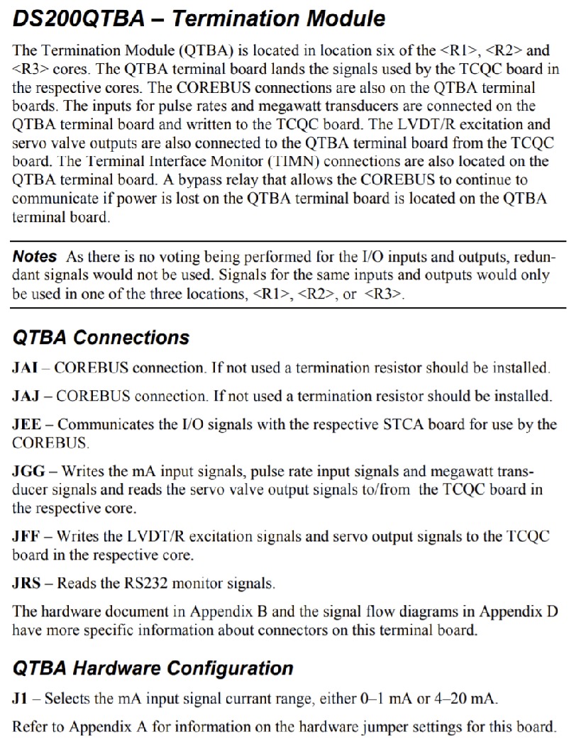
The configuration for the DS200QTBAG1ADC is in core <R>, <S>, <T>, in location 6. It has a single jumper in position J1 that will modify the input signal selection. The default position of this jumper is in the 20mA position. Unfortunately, this is about the extent of DS200QTBAG1ADC hardware information available upon an inspection of its available original instructional manual materials. With this in mind, the DS200QTBAG1ADC functional product number gains a new relevance, as it displays this DS200QTBAG1ADC product's more-relevant hardware inclusions in consecutive functional naming chunks. The DS200QTBAG1ADC functional product number begins with the DS200 series tag asserting this DS200QTBAG1ADC PCB's normal Mark V Series assembly and its domestic original manufacture location. The QTBA functional product abbreviation in this DS200QTBAG1ADC PCB's functional product number is followed by another naming chunk with dual responsibilities in the G1 series grouping tag delegating this DS200QTBAG1ADC PCB's normal PCB coating style and its group one Mark V Series product grouping. The three final alphanumeric digits in the DS200QTBAG1ADC functional product number are telling of this DS200QTBAG1ADC PCB's three significant product revisions, including two functional revisions and an artwork configuration revision. The DS200QTBAG1ADC instructional manual materials above do make mention of a few unique specifications for this DS200QTBAG1ADC product here. When this DS200QTBAG1ADC device's various inputs and outputs are not holding voting, this DS200QTBAG1ADC Board's various redundant signals will not be accessed. Only the R1, R2, or R3 locations in the greater Mark V Series automated drive assembly would utilize signals for these mentioned inputs and outputs.


