About the DS200QTBAG1B
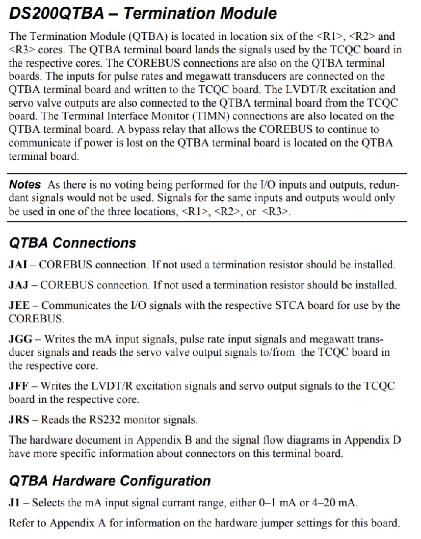
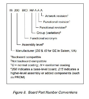
The DS200QTBAG1B is a printed circuit board component part designed for application in a greater Mark V Speedtronic Series drive assembly. This product functions specifically as a RST Termination board, and is outfitted with a series of jumpers and connectors for compatibility's sakes. This board uniquely includes a singular functional revision rated at a "B" grade, and may be referred to solely by its functional industry acronym "QTBA" in industry circles. This product is considered a printed circuit board, making it applicable to our AX Control Guaranteed three-year warranty upon purchase. The Mark V Series that this DS200QTBAG1B PCB was manufactured for is considered a now-obsolete legacy product series, given its eventual manufacturing discontinuation taking place in the many years past its initial release.
Hardware Tips and Specifications
The GE RST Termination Board DS200QTBAG1B, like many other similar printed circuit board models, comes standard with a unique series of drive components that contribute to its overall functionality. With this model's "B"-rated functional revision in mind; the DS200QTBAG1B features a series of special components including:
- 2 terminal blocks with terminals for 72 signal wires in each
- 1 JFF-labeled 40-pin connector
- 1 serial connector.
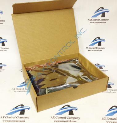
Beyond these basic specifications, the GE RST Termination Board DS200QTBAG1B is also populated with 1 3-pin jumper, although additional explanation is needed to be fleshed out for this jumper. The jumper covers 2 of the 3 pins on the board to enable a configuration option. When the original board from the factory is installed in the drive, the installer must refer to the documentation that comes in the carton for information concerning the jumper, to ensure voltage safety. If pins 1 and 2 are covered by the jumper, the board is configured to process information as defined by that jumper configuration. If pins 2 and 3 are covered by the jumper, the board processes information as defined by that configuration. Some jumpers cannot be moved to change the configuration because only one configuration is supported. The other configuration is for factory use only or is used in a configuration that will be supported in a future version of the board. For example, an unsupported configuration might be used at the factory for product testing during manufacturing. Or, the board is populated with a jumper with only 1 supported function, the other function being implemented in a future version of the board. To change the position of the jumper, lift up the jumper with your thumb and forefinger. Then, align the jumper with the pins you want to cover and press the jumper over the pins.


