About the DS200QTBAG3ADC
This DS200QTBAG3ADC printed circuit board was originally manufactured for the Mark V Turbine Control System Series, as explained briefly above. The Mark V Series, as you have probably been able to gather by its full extended series name, has specific applications in the control and management systems of gas, steam, and wind turbine automated drive assemblies. The Mark V Turbine Control System Series that this DS200QTBAG3ADC Board belongs to is considered a legacy series discontinued by its original manufacturer, although the Mark V also exists as one of the final General Electric Mark product series to make use of the company's patented Speedtronic control system technology. While this DS200QTBAG3ADC printed circuit board product offering is recognizable as a Termination Module based on this functional description's presence in the DS200QTBAG3ADC PCB's original instructional manual materials, it is not the first product of this functionality to be offered in the Mark V Turbine Control System Series; that would be the DS200QTBAG3 parent Termination Module missing all three of this DS200QTBAG3ADC product's significant product revisions.
Hardware Tips and Specifications
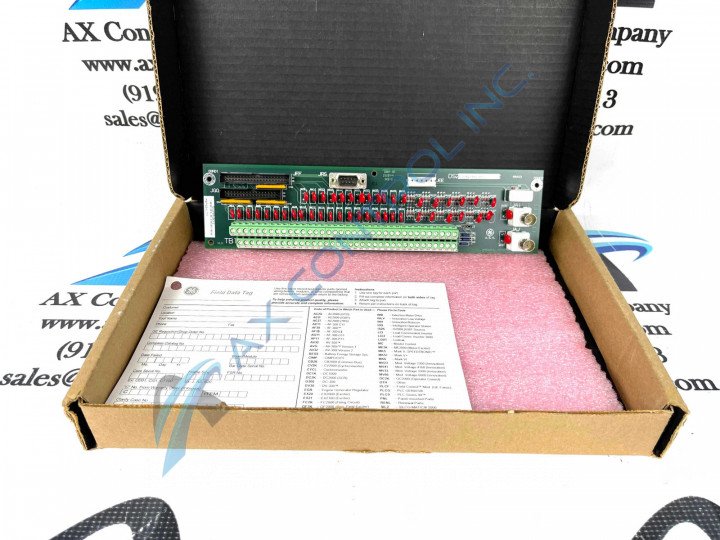
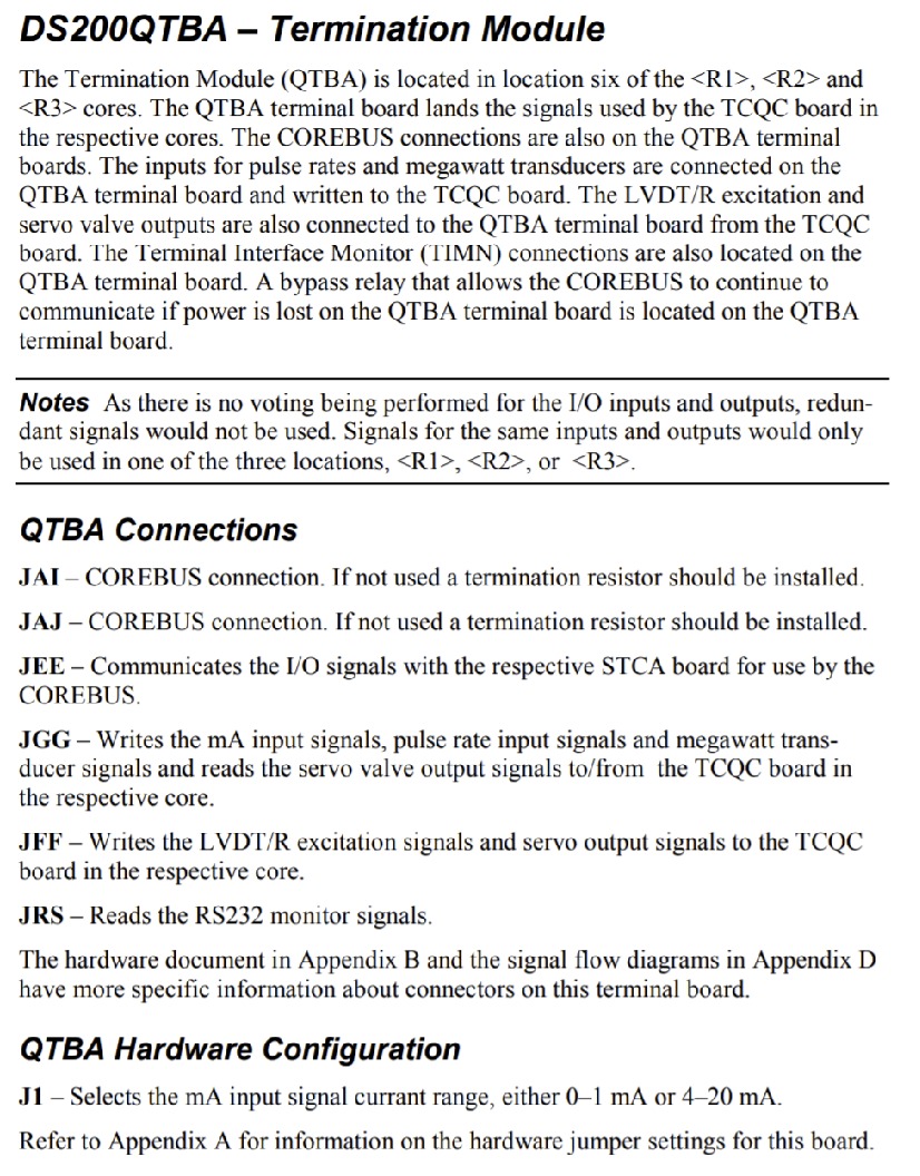
The GE RST Termination Board DS200QTBAG3ADC features 2 terminal blocks with terminals for 72 signal wires in each. It also contains 1 40-pin connector. The ID for the 40-pin connector is JFF. It also is populated with 1 serial connector. The 40-pin connector is used to connect to a ribbon cable. The ribbon cable carries signals that are transmitted to the board from other components. Alternatively, the ribbon cable carries signals that the board transmits to other boards and components. During normal processing, the boards receive signals from other boards and processes the information before sending on the information to another board or component. The ribbon cables for the 40-pin connector contains 40 separate signals on 40 separate small strands of fine copper wire. You will also notice that little support is provided between the plastic connector and the ribbon cable. For that reason, it is best practice to not pull on the ribbon cable to disconnect it from the board. It is easy to pull the fine copper wires out of the plastic connector. Instead, hold the plastic connector with one hand and gently pull it out of the connector on the board. To connect a ribbon cable, align it with the connector on the DS200QTBAG3ADC board and press it into the connector. If you visually inspect the connection and you see space between the ribbon cable and the connector on the board, the cable might not be fully seated. In that case, gently press the ribbon cable until it is fully seated.
The DS200QTBAG3ADC board-specific hardware tips and specifications inserted above are somewhat disproportionately focused on this DS200QTBAG3ADC product offering's ribbon cable connections, given that these ribbon cables are some of the only DS200QTBAG3ADC board hardware components discussed in detail in its original instructional manual documentation. This DS200QTBAG3ADC product's low online availability of these original instructional materials means that the DS200QTBAG3ADC functional product number itself gains a new value, beginning with the details revealed in its DS200 dual-functional series tag. The DS200 series tag at the very beginning of the DS200QTBAG3ADC functional product number is telling of this DS200QTBAG3ADC PCB's normal Mark V Series assembly version as well as its domestic location of original manufacture. Some of the other hardware details and specifications revealed in functional chunks of the DS200QTBAG3ADC product number include this DS200QTBAG3ADC Termination Module's:
- Normal Mark V Series assembly version
- Domestic location of original manufacture
- QTBA functional product acronym
- Normal PCB coating style
- Group 3 Mark V Series product grouping
- A-rated primary functional revision
- D-rated secondary functional revision
- C-rated artwork configuration revision


