About the DS200RTBAG2A
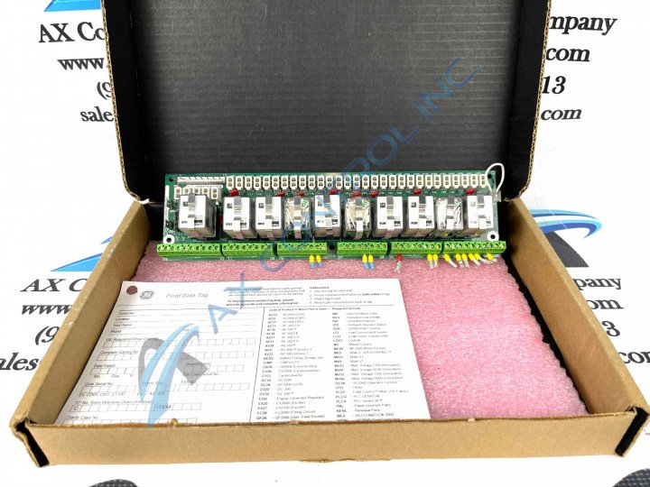
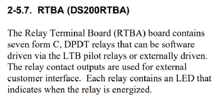
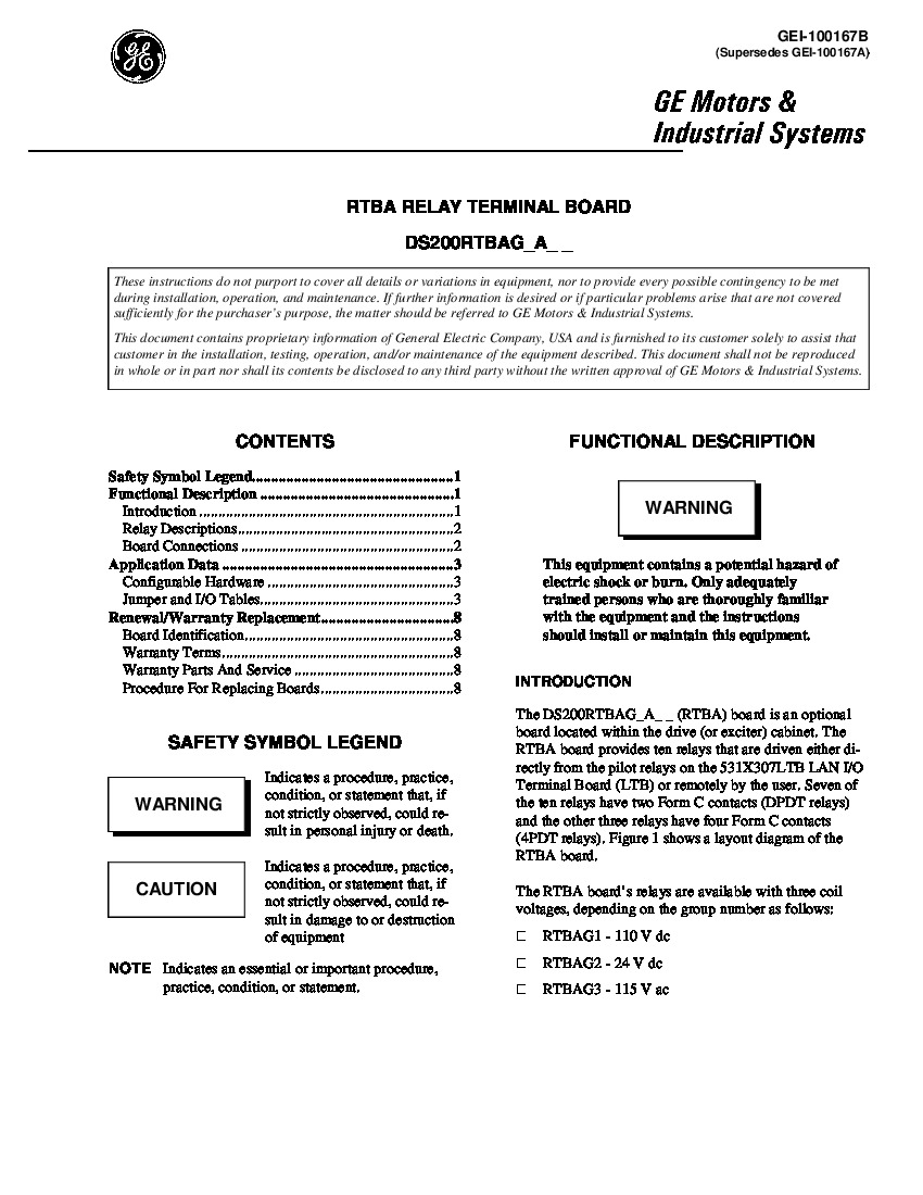
General Electric’s DS200RTBAG2A is a RTBA, or relay terminal board, designed for the Mark V board series. The Mark V Series that this DS200RTBAG2A product offering belongs to is a series of automated drive assemblies and assembly components that have specific applications in the control and management systems of wind, gas, and steam turbines. The Mark V Series, while one of the more recently-developed General Electric product series utilizing their patented Speedtronic technology in its products. When installed, this DS200RTBAG2A board provides an additional ten relay spots to its installed host, which likely contributes to its official functional product desription as a Relay Terminal Board. This card can be installed in the cabinet of a wide variety of GE brand exciters and drivers. Both remote and LAN I/O terminal control is possible when using this RTBA board.
Hardware Tips and Specifications
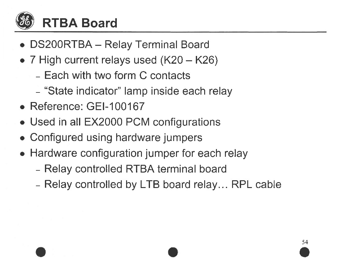
As alluded to earlier, the specific set of functional hardware components and component specifications in the assembly of this DS200RTBAG2A PCB all contribute towards its originally-intended Mark V Turbine Control System Series functionality. The ten relays found on the board are comprised of two types, DPDT and 4PDT. Seven DPDT type relays are found on the board, each containing two Form C contacts. Each contact on the relay registers a 10A charge, and a 110 VDC coil is also found within each relay. In regards to placement on the DS200RTBAG2A board, each DPDT relay can be found between locations K20 and K26. The 4PDT relay types comprise the final three spots on the board. These types consist of four contacts within each relay. Contacts within these types feature a 1A charge. Each relay also contains a 110 VDC coil, and all onboard relays are protected by a 130 VAC metal oxide varistor (MOV). Users can easily remove and replace relays as needed.
Installation parameters for both the drive and the board should be followed by users. These will ensure that both DS200RTBAG2A and the drive system operates as intended. To review a wiring and installation guide, please refer to the board’s manual and datasheet, attached in the manuals tab above. For your convenience and for supreme customizability, a series of manually-moveable hardware jumpers have been worked into the assembly of this DS200RTBAG2A PCB, as detailed in the DS200RTBAG2A PCB's instructional manual. Each one of these customizable pieces of hardware is accompanied by its own factory-printed nomenclature label beginning with the J tag designating a jumper component. Some of the crucially-important jumpers to the normative daily functionality of this DS200RTBAG2A printed circuit board include the JP8 K20-K22 Power Source-Selecting Jumper and the JP9 RPL. 1 Connection Jumper. All of the various hardware components and set component specifications included in the assembly of this DS200RTBAG2A Relay Terminal Board should be well-protected in some quantity thanks to the normal style of PCB surface coating applied to this product, which exists as a thick rudimentary protective layer. This DS200RTBAG2A PCB's original performance specifications and dimensions have no doubt been altered as a function of its A-rated functional product revision.


