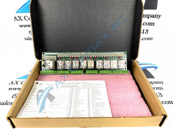
About the DS200RTBAG2AGC
The DS200RTBAG2AGC serves as a relay terminal board operating at 24 VDC. It is specifically designed for integration into General Electric's Mark V turbine control system. The Mark V system belongs to the Speedtronic series, a line of industrial turbine control systems developed by General Electric, starting from Mark I and continuing through Mark VI. Speedtronic systems are engineered to provide control, protection, and management capabilities for industrial turbine systems. The Mark V Series, despite existing as a manufacturer-discontinued legacy product series, has attracted something of a cult demand on its greater figurative automated industrial marketplace, given the fact that it is one of the later renditions of General Electric Mark product series to make use of the patented Speedtronic control system technology across a range of offerings. The Mark V Series was discontinued for production due to a manufacturer-identified functional series obsolescence in one of the many years beyond its initial Mark Series rollout.
Hardware Tips and Specifications
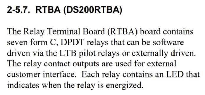
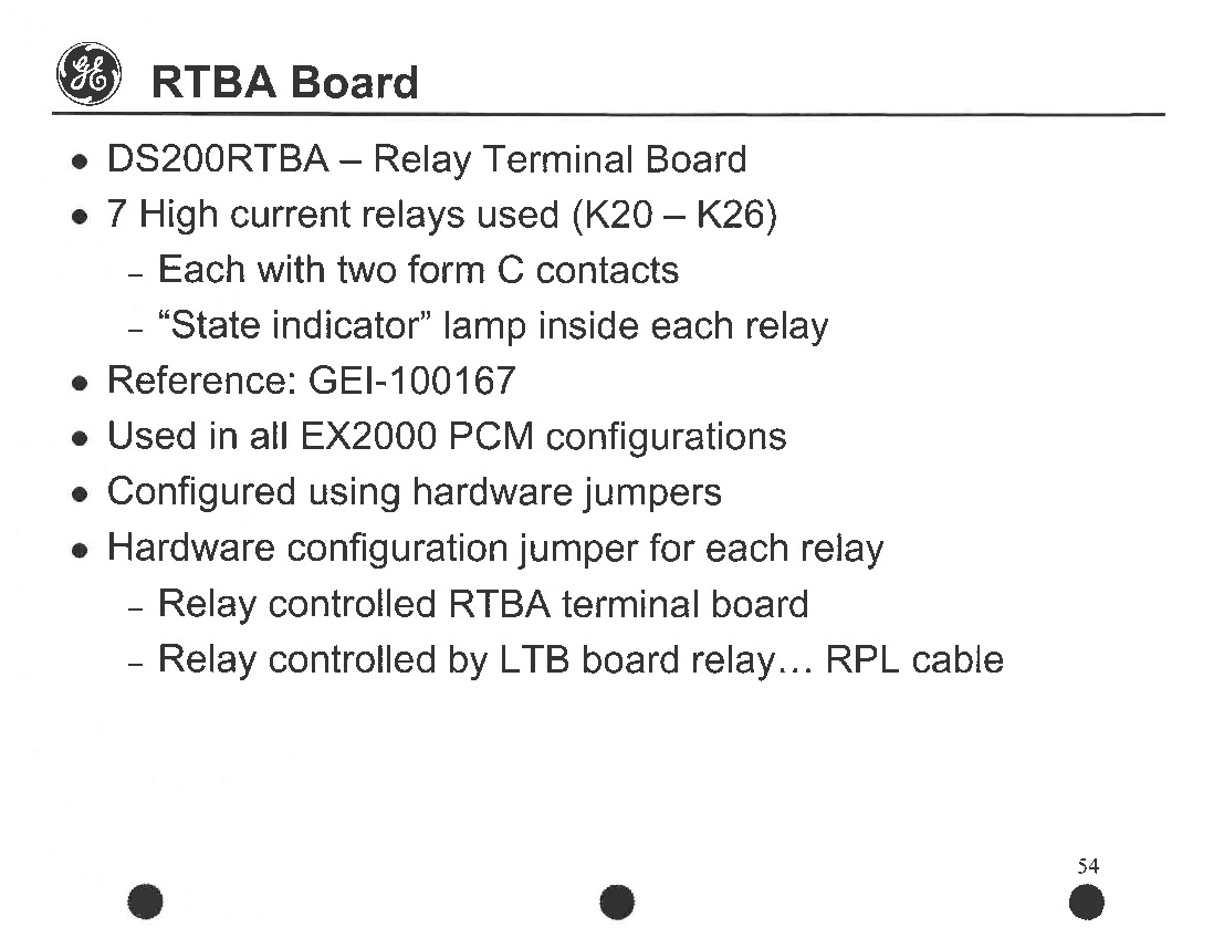
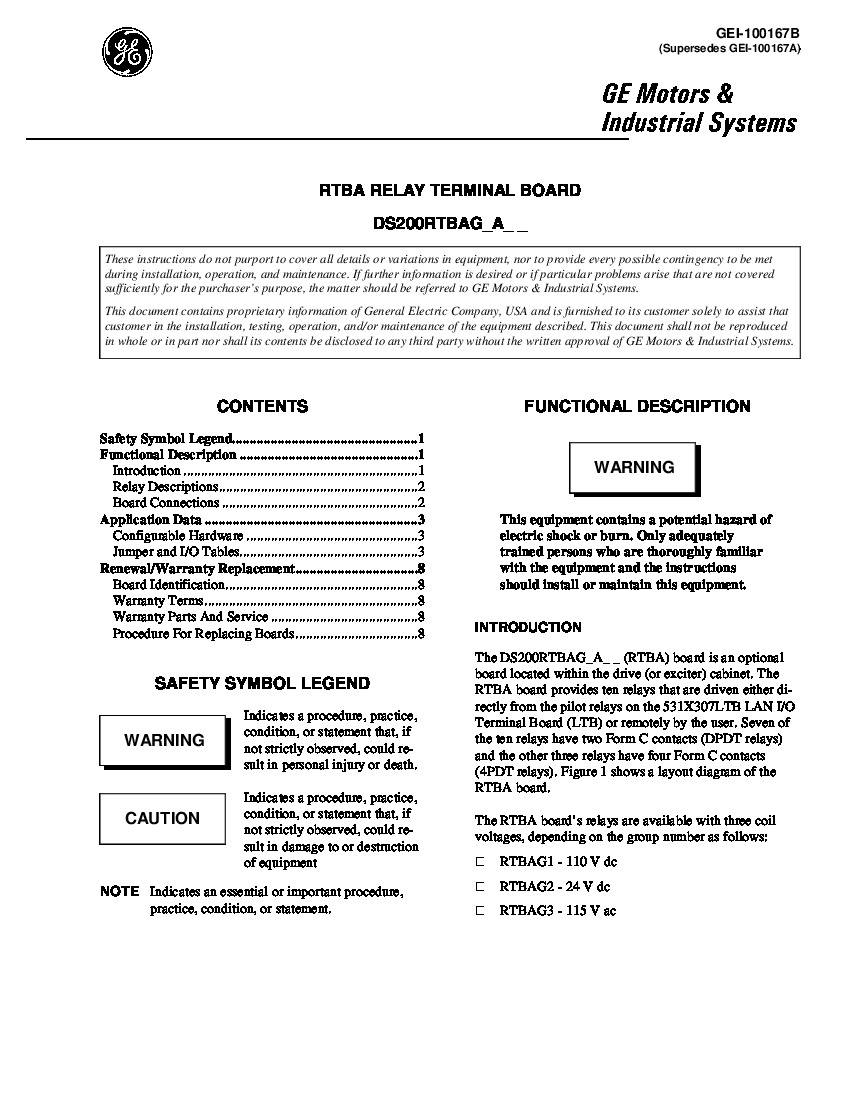
In addition to the DS200RTBAG2AGC 24 VDC relay board, AX Control also offers alternative options such as 110 VDC and 115 VAC relay boards. If you require these alternative voltages, please explore our inventory for the RTBAG1 and RTBAG3 boards. The DS200RTBAG2AGC is an optional component that is typically situated within the drive or exciter cabinet. However, it can also be operated remotely by the user or through pilot relays on the LAN I/O terminal board (531X307LTB). Out of the ten relays on the board, two have two Form C contacts, while three relays possess four Form C contacts. Generally, this DS200RTBAG2AGC device can be described as a highly-customizable product offering from the Mark V Series, given the strong offering off many different Berg-type manually-moveable hardware jumpers, which are customizable. Most of these jumpers select for either coll voltage sources or for CPH/CPN pluggable circuits. Each relay on the board is equipped with an LED that illuminates to indicate its activation. This DS200RTBAG2AGC device's connectors, of which it possesses many, are all defined in the DS200RTBAG2AGC instructional manual in terms of their functionality and their respective factory-printed nomenclature labels. For instance, this DS200RTBAG2AGC device's stab connectors include:
- The RTBA Board CPH Pluggable circuit control power positive side (hot) connector
- The RTBA Board CPN Pluggable circuit control power negative side connector
To ensure compatibility, the DS200RTBAG2AGC includes multiple Berg-type hardware jumpers that are shipped with default settings. Nevertheless, it is essential to verify the jumper settings against your existing board component if you are replacing it, ensuring that all jumpers are positioned identically. For detailed information regarding the DS200RTBAG2AGC, GE provides manuals such as GEI-100167B, which contains comprehensive tables with jumper descriptions, connector RPL pin descriptions, connector OPTPL pin descriptions, and stab connector descriptions. It is crucial to thoroughly read and comprehend this information before unpacking your part. For your convenience, this DS200RTBAG2AGC device's originally-printed instructional documentation has been embedded in our manuals tab above. This DS200RTBAG2AGC PCB product, while existing as a Relay Terminal Board in its own right, is actually not the originally-developed product of this specific Mark V Series functionality; that would be the DS200RTBAG2 parent printed circuit board notably missing this DS200RTBAG2AGC device's full three-fold revision range. This DS200RTBAG2AGC device is a highly-supported Mark V Series product in terms of its diagnostic fault detection support. For instance, each individual relay in the normal assembly of this DS200RTBAG2AGC Relay Terminal Board is accompanied by its own state indicator lamp, which in a self-explanatory turn, indicate normative functional states of this DS200RTBAG2AGC device's individual relays. When a DS200RTBAG2AGC Board relay state indicator lamp does not glow, that means that the individual relay is not energized, for any number of functional fault reasons.


