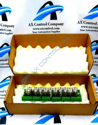
About the DS200RTBAG3ADB
This DS200RTBAG3ADB General Electric printed circuit board product offering was originally manufactured for use in the Mark V Series. As alluded to above, the Mark V Series is a General Electric legacy series formerly manufactured to function in specific control and management systems of wind, steam, and gas turbine automated drive assemblies. The Mark V Series is considered a legacy series as its manufacturing has been discontinued by General Electric in the years following its initial release. While considered a legacy series, the Mark V Turbine Control System Series that this DS200RTBAG3ADB Board belongs to is also definable as one of the final General Electric product series to incorporate the company's patented Speedtronic technology in its products. This DS200RTBAG3ADB printed circuit board or PCB for short is actually more explicitly-definable as a Relay Terminal Board; the official functional product description it is referred to as in original General Electric and Mark V Series instructional manual documentation. While this DS200RTBAG3ADB PCB does exist as a Relay Terminal Board in its own right, it is by no means considered the original product of this functionality created for use in the Mark V Turbine Control System Series; that would be the DS200RTBAG3 parent Relay Terminal Board missing all three of this DS200RTBAG3ADB product's three significant revisions.
Hardware Tips and Specifications
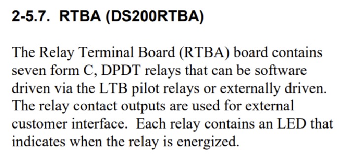
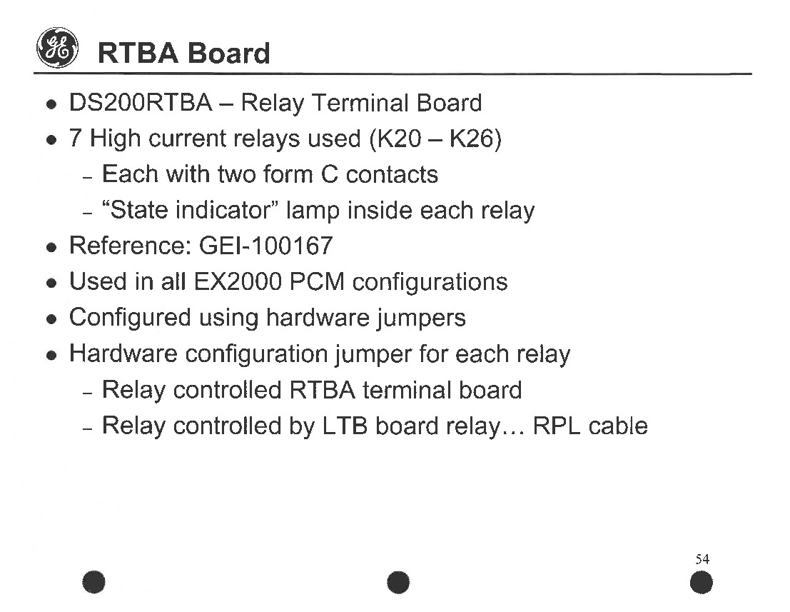
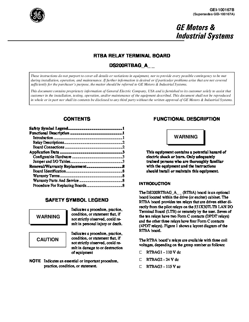
The General Electric Power Excitation Board DS200RTBAG3ADB is an optional board that is installed in the drive cabinet and it features ten relays that are driven either directly from the plot relays or remotely by the user. Given the optional status of this DS200RTBAG3ADB product offering, paired with its specific and crucial functionality, the DS200RTBAG3ADB board necessitates its own series of hardware component inclusions and specifications. Seven total relays are utilized for general voltage limitation purposes in the assembly of this DS200RTBAG3ADB Relay Terminal Board. Each of these relays exists as a High Current Relay, with each relay marked by individual factory-printed nomenclature labels ranging from K20-K26. Each of these relays has two total form C-type contacts, and is accompanied by a state indicator lamp that, well, indicates the state of each relay. When glowing or lit, the relay indicator lamps convey an active current supplied to their respective relay. This DS200RTBAG3ADB printed circuit board or PCB for short has a functional General Electric product number that reveals additional hardware specification information. Some of the DS200RTBAG3ADB board hardware details embedded in the DS200RTBAG3ADB functional product number itself include this DS200RTBAG3ADB PCB's normal assembly type, domestic manufacture location, RTBA functional product acronym, normal style of PCB coating, group three Mark V Series grouping, and finally its three-fold product revision history.
When you replace the DS200RTBAG3ADB board, one important task is to remove all the cables and wires from the old board that has become defective and reinstall them on the new board. The board will provide unreliable behavior or will appear to be defective if the wires and cables are not installed properly; luckily for us, General Electric supplies detailed instructions on the installation process of the DS200RTBAG3ADB PCB. Write down the connector numbers that have wires or cables attached to them and also record what cable is connected to them before you disconnect the cables. Before you start the replacement, you must turn off the drive. From the control panel you can use the keypad to manually shut down the motor and stop all operations. Consult with the service personnel on the best method to turn off power to the drive. The site has 3-phase power supplies that power the drive and you can disable the power supplies to discontinue the power to the drive. Use a voltage tester to confirm that all power is removed from the drive.


