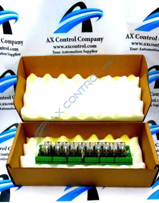
About the DS200RTBAG3AEB
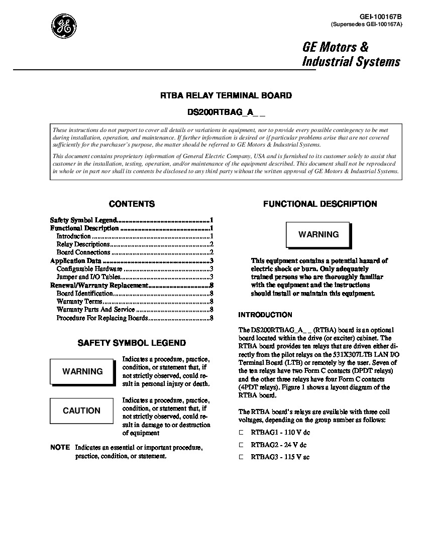
This DS200RTBAG3AEB printed circuit board was originally manufactured for General Electric's Mark V Turbine Control System Series; a General Electric legacy series given the Mark V's manufacturing discontinuation in the years following its initial release. The Mark V Series, as you can probably tell by its full extended series name, has specific applications in the control and management systems of popular wind, steam, and gas turbine automated drive assemblies, and is one of the final General Electric product series to make use of the company's patented Speedtronic control system technology first introduced with the rollout of the Mark I in the late 1960s. This DS200RTBAG3AEB printed circuit board product offering is truly better-describable simply as a Relay Terminal Board; the official functional product description it retains in original Mark V Series instructional manual materials. While this DS200RTBAG3AEB PCB is definable as a Relay Terminal Board in its own right, the originally-developed product within the Mark V is the DS200RTBAG3 parent printed circuit board missing all three of this DS200RTBAG3AEB PCB's significant product revisions.
Hardware Tips and Specifications
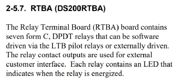
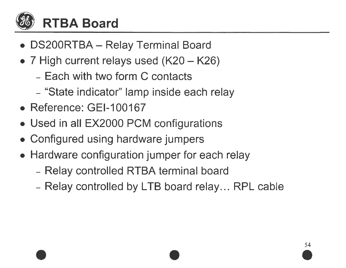
The GE Power Excitation Board DS200RTBAG3AEB is an optional board that is installed in the drive cabinet and it features ten relays that are driven either directly from the plot relays or remotely by the user. Even as a Mark V Series option board, this DS200RTBAG3AEB product necessitates its own series of functionality-inducing hardware components and component specifications. The DS200RTBAG3AEB contains 52 terminal points that you can use to attach wires that control the behavior of the relays and the drive through signals. Seven total relays have been included in the assembly of this DS200RTBAG3AEB Relay Terminal Board. Each of these aforementioned relays in the assembly of this DS200RTBAG3AEB product is accompanied by their own state indicator lamp and two form C contacts, and are all labeled by factory-printed nomenclature labels. In terms of customizable hardware in the assembly of this DS200RTBAG3AEB printed circuit board, this Mark V Turbine Control System Series product offering makes use of a singular hardware configuration jumper attached to each individual relay in its assembly. The state indicator lamps attached to each relay in this DS200RTBAG3AEB PCB's internal assembly glow to indicate an energized relay status. It is important to remember that the relays in the assembly of this DS200RTBAG3AEB product offering may possess lasting and potentially-damaging voltages even minutes after the DS200RTBAG3AEB PCB's greater Mark V Turbine Control System Series automated drive assembly is powered off.
Diagnostics are available on the drive if you have a need to verify the relays are setup correctly or if you suspect a problem with the drive or the DS200RTBAG3AEB board. You can access the diagnostics from the control panel. Keys on the keypad enable you to access the diagnostics. The diagnostics provide an inclusive report on the drive and all the boards. You might find it easier to download the report to a laptop where you can save it, print it on paper, or search through it. After you determine that the board must be replaced, do not touch the boards in the drive or any components in the drive until you have disconnected all power. High-voltage current is in the drive and after you disconnect power you must wait 5 seconds for the current to leave the components. Test the boards and other components for the presence of current. Don’t touch anything until you are sure the current has exited. Some components store current while the board is electrified and in use. Waiting after the DS200RTBAG3AEB Relay Terminal board is disconnected provides time for the current to dissipate. Before making any final purchase decision on this DS200RTBAG3AEB product, it is crucial to realize that its originally-introduced performance specifications and dimensions have been impacted by its possession of three significant revisions including an A-rated functional product revision, an E-rated functional product revision, and a B-rated artwork configuration revision.


