About the DS200RTBAG3AFB
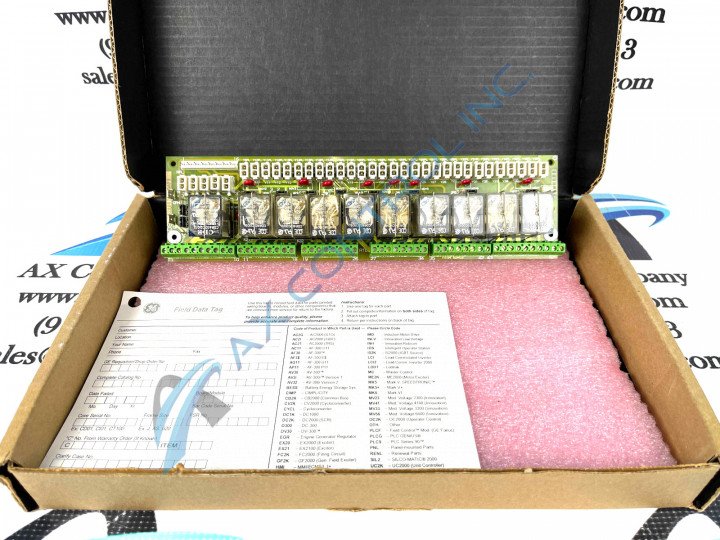
The General Electric Power Excitation Board DS200RTBAG3AFB is an optional board that was designed for installation in a drive cabinet assembly. This printed circuit board component was specifically manufactured for use in a greater GE Fanuc series drive assembly. The baseplate of this PCB component part is affixed with ten total relays and numerous customizable hardware components. This product is considered a member of a General Electric legacy series, as its original manufacturer has discontinued mass production of this product in recent years. This product is protected under our guaranteed 3-year AX Control warranty upon purchase.
Hardware Tips and Specifications
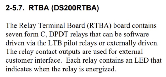
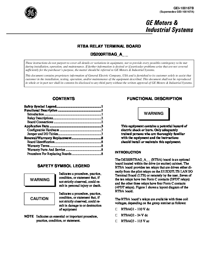
The primary function of this model of PCB exists in its careful placement of a series of relays. The DS200RTBAG3AFB features ten relays that are driven either directly from the plot relays, or remotely by the drive assembly user. Whereas the majority of other GE Power Excitation Boards use 110V dc or 24V dc coil voltages, this DS200RTBAG3AFB model has a number of relays fitted with 115V ac coil voltage.
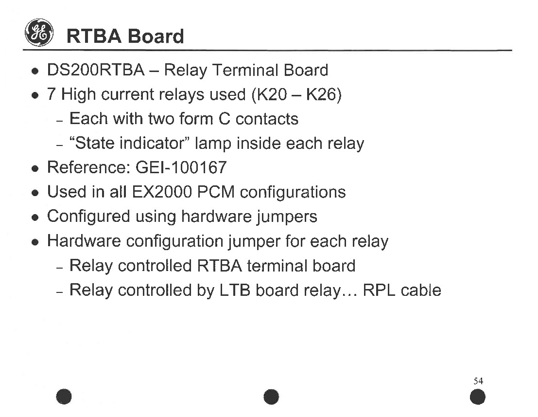
This specific board also offers jumpers you can use to configure the board to work for your application. Typically, jumpers enable you to use an external power source or an internal power source for each relay. The external power source is supplied by the greater drive assembly's terminal board.
Beyond these jumpers, a mentionable specification for the DS200 RTBA can be named in the different connectors attachable to the base plate of the PCB. The terminal on the board has connector slots for up to 52 connectors; each connector being secured by individual screws. To remove a wire, the drive assembly administrator must loosen the screw, while being careful to not remove it entirely. It is very important to label the wires so you can quickly reconnect them correctly to the new board. Some of the more relevant connectors compatible with this Fanuc series product include:
- CPH and CPN stab connectors
- Y9-Y35 connectors
- K20-K26 connectors
- a 115 V connector
- RX1-RX7 connectors
- an X2 connector
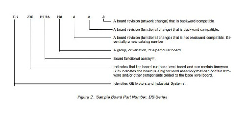
Other relevant connector types compatible with the DS200RTBAG3AFB are described above in the General Electric manual GEI-100167B. A final significant hardware trait unique to this model of printed circuit board component can be derived from its part number. The "G3" portion of the DS200RTBAG3AFB component board's part number designates it both as a group 3-style PCB and as a normally-coated printed circuit board. Normally, coated printed circuit boards, while protected by a thick layer, typically don't offer the same vast protective coverage as their conformal-coated counterparts.
Installation Tips and Specifications
As with many static-sensitive PCB component parts from the GE Fanuc series, the manufacturer has supplied us with some important recommendations for correct and safe installation of the DS200RTBAG3AFB. One important consideration for installation of this PCB is that when you install the board in the greater drive assembly, it is critical to remove some screws and washers that secure the board in the drive. As you remove the screws and washers to remove the board, do not allow the metal hardware to fall into the drive and get lost. Keep track of all the hardware and store it in a safe until you need it. Loose metal parts might cause a safety hazard or might damage the drive or components due to both the drive's moving internal assembly and its high-voltage current.
Another suggestion important to consider when attempting installation of the RTBA PCB component are the various plastic holders and clips that help keep the RTBA component board attached to the greater drive assembly. This drive's CP1PL-CP5PL and Y9PL-Y37PL connectors are all held in place through the use of integral holding clips. To release these connectors from their wired positions, the drive assembly administrator must press the assembly's connector lever. Some cables have pull tabs that should always be pulled gently for release purposes.


