About the DS200RTBAG4RHC
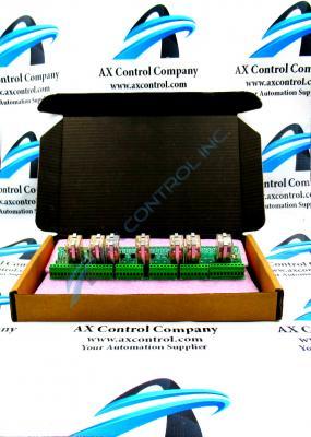
This DS200RTBAG4RHC printed circuit board was originally manufactured to exist as a member of General Electric's Mark V Turbine Control System Series, as mentioned above. The Mark V Series that this DS200RTBAG4RHC printed circuit belongs to has specific applications in the management and control systems of popular steam, wind, and gas turbine automated drive assemblies, and is one of the latest-developed General Electric product series to make use of their patented Speedtronic style of control system technology. While this is true, this DS200RTBAG4RHC printed circuit board's greater Mark V Turbine Control System Series has to be considered a legacy General Electric product series given its manufacturing discontinuation in the years following its initial General Electric release. This DS200RTBAG4RHC printed circuit board is truly better-definable as a Relay Terminal Board; the official functional product description that it attains in original Mark V Series instructional documentation.
Hardware Tips and Specifications
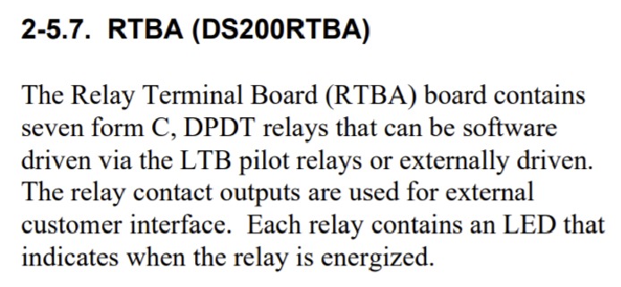
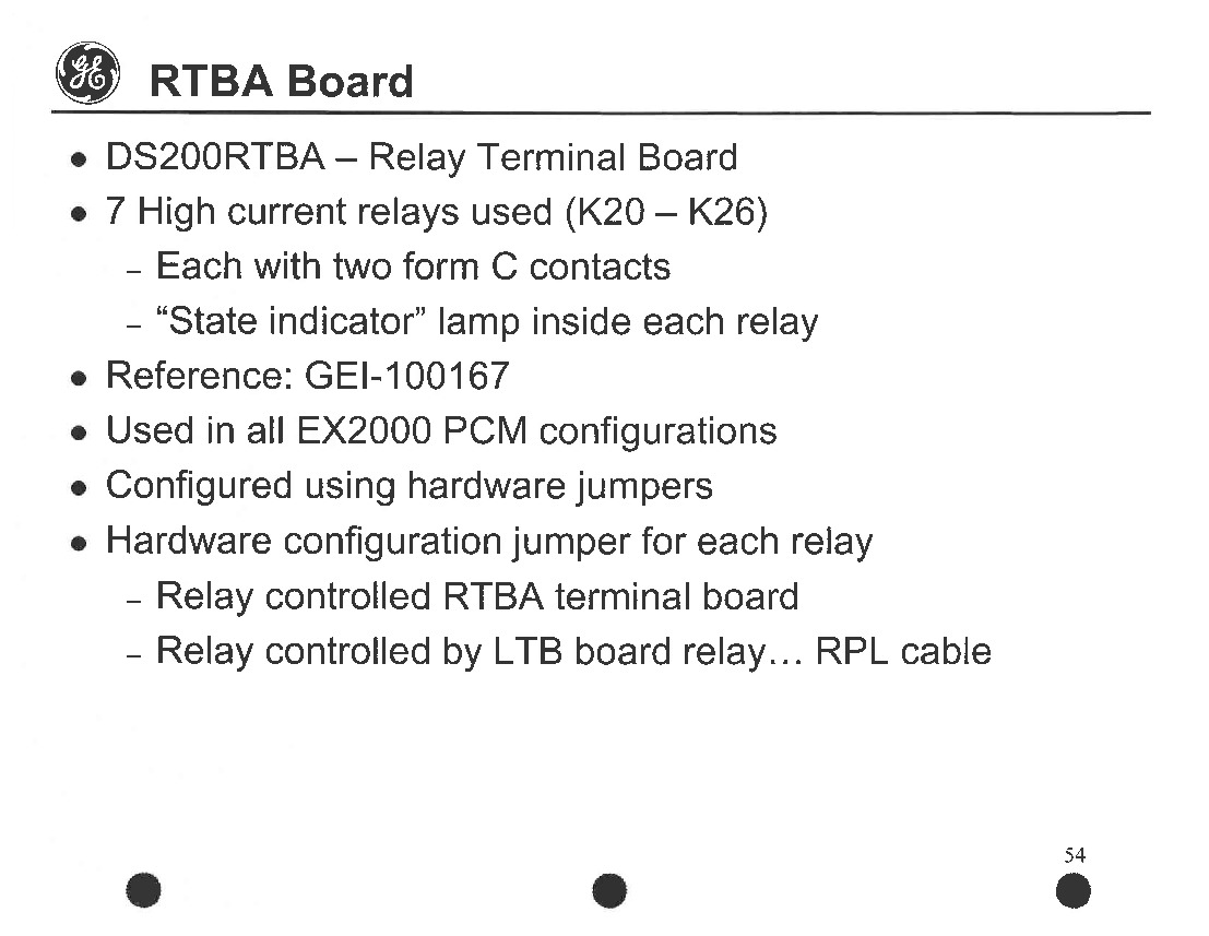
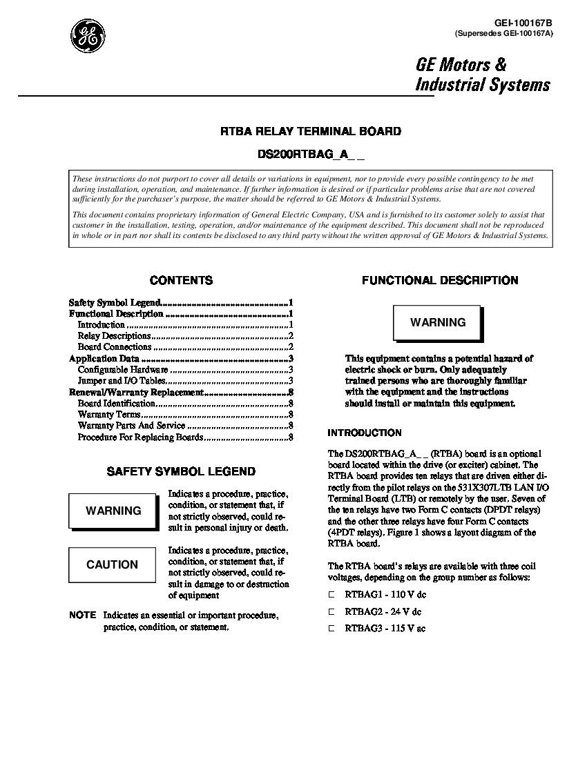
The GE Power Excitation Board DS200RTBAG4RHC is an optional board that is installed in the drive cabinet and it features ten relays that are driven either directly from the pilot relays or remotely by the user. The DS200RTBAG4RHC board has multiple jumpers that enable you to control the behavior of the board, wire connectors for pluggable circuits, cable connectors, ribbon cables, and stab connectors for pluggable circuit power. Each individual hardware component in this DS200RTBAG4RHC product offering's assembly is accompanied by its own factory-printed nomenclature label as detailed in the DS200RTBAG4RHC application manual available above. For example, the two stab connectors in the assembly of this DS200RTBAG4RHC product offering are labeled as CPH and CPN. The DS200RTBAG4RHC PCB's CPH stab connector is labeled as such given it controls pluggable circuit control power positive side (hot) for RTBA Board pluggable circuits, and the DS200RTBAG4RHC PCB's CPN connector is labeled as such given its functionality on the power negative side for these same pluggable circuits.
Before you disconnect any cables or wires in the assembly of this DS200RTBAG4RHC PCB, it is vital that you note where all the wires and cables are connected on the defective board. Make labels that indicate where a cable or wire is connected before you disconnect it. The connectors all have identifiers on the board and they provide a precise and easy means of identification. DS200RTBAG4RHC ribbon cables are especially fragile and require that you understand the proper procedure to connect and disconnect them. The thin wires that make up each signal on the ribbon cable is easily damaged and can be disconnected from the connector. Hold the ribbon cable only from the connector with one hand and hold the connector on the board with the other hand. Pull them apart to disconnect. The RTB terminals on the board are held in place with small screws that hold the terminals securely. To unfasten them, use a screwdriver to loosen the screw and pull out the wire. Don’t remove the screw entirely from the terminal but do leave it in the terminal. If it does fall out retrieve it so that it doesn’t get lost in the drive. Before making any final purchase decision on this DS200RTBAG4RHC product offering, it is absolutely crucial to understand that this DS200RTBAG4RHC PCB's originally-introduced performance specifications and basic dimensions have almost surely been altered as a function of its possession of a full range of three total significant product revisions including two functional revisions and a singular artwork configuration revision.


