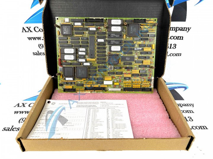
About the DS200SDCCG1A
This DS200SDCCG1A printed circuit board was originally manufactured for placement in the Mark V Turbine Control Systems Series produced originally by General Electric. This DS200SDCCG1A PCB's greater Mark V Series, as indicated by its full name, has specific applications in the management and control systems of wind, steam and gas turbine automated drive assemblies. The Mark V Turbine Control System Series that this DS200SDCCG1A PCB belongs to is additionally considered to exist as a General Electric legacy series, as its manufacture has been discontinued in the years following its immediate release. The Mark V Turbine Control System Series, while considered to exist as a legacy series, is one of the final General Electric Mark product series to make use of the patented Speedtronic control system technology. This DS200SDCCG1A PCB makes use of a singular A-rated functional product revision altering it from the original DS200SDCCG1 parent printed circuit board also existing as a Drive Control Board in its greater Mark V Series automated drive assembly.
Hardware Tips and Specifications
The General Electric Drive Control Board DS200SDCCG1A is the primary controller for the drive, and possesses its own elevated number of hardware components and component specifications to meet this primary status. The GE Drive Control Board DS200SDCCG1A is populated with 3 microprocessors and RAM that can be accessed by multiple microprocessors at the same time. One microprocessor in this DS200SDCCG1A PCB's assembly is for drive control functions and it contains many built-in functions and uses digital and analog I/O. It also contains the user interface software. One other microprocessor present in this DS200SDCCG1A Drive Control Board's assembly is used for high-speed I/O, digital I/O, analog I/O, and a digital timer, and is additionally used for math-intensive functions for motor control processing. The GE Drive Control Board DS200SDCCG1A contains multiple connectors that transmit and receive signals to other boards in the drive. When you connect the cables, you must take care to route the cables so that they do not touch other components in the drive. Also, it is best practice to label the cables so that it will be easy to replace the board, if necessary. Finally, it is best practice to create the labels while the connector identifiers are easily available.
Consider the following information before you replace the General Electric Drive Control Board DS200SDCCG1A. The board is designed to support auxiliary boards that are mounted on the GE Drive Control Board DS200SDCCG1A. The auxiliary boards are connected directly to connectors on the board and they provide added functionality to the board. However, before you replace the board, remove the auxiliary board first. Then, install the auxiliary board on the replacement GE Drive Control Board DS200SDCCG1A. Before making a final purchase decision on this DS200SDCCG1A PCB, it is important too to consider some of the various voltage limitation strategies that it adopts, as it is classified by its original General Electric manufacturer as a static-sensitive product offering. All of the factory-drilled installation holes in the assembly of this DS200SDCCG1A printed circuit board have been ringed with an insulated material in observance of potentially-present damaging DS200SDCCG1A board surface voltages. The entirety of this DS200SDCCG1A Drive Control Board's base circuit board should be protected and somewhat insulated by this Mark V Series product offering's normal style of PCB coating, which exists as a thick rudimentary layer of chemically-applied PCB protection that envelops, insulates, and protects individual hardware components in this product's assembly on a functional priority basis.


