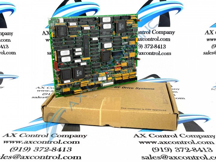
About the DS200SDCCG1AFD
This DS200SDCCG1AFD Drive Control Board was originally manufactured for the Mark V Turbine Control System Series of respected industrial retailer General Electric. As you can more than likely tell by its full extended name, this DS200SDCCG1AFD product's greater Mark V Series has specific applications in the control and management systems of compatible wind, steam, and gas turbine automated drive assemblies, and is considered a GE legacy series given its eventual discontinuation in the years following its initial release. This DS200SDCCG1AFD PCB's Mark V Series, while a General Electric legacy series, is also one of the final GE product series to make use of their patented Speedtronic control system technology. While this DS200SDCCG1AFD PCB is certainly definable as s Drive Control Board in its own right, the originally-developed product of this functionality to exist within the Mark V Series is the DS200SDCCG1 parent Drive Control Board.
Hardware Tips and Specifications
The GE Drive Control Board DS200SDCCG1AFD is the primary controller for the Mark V Series automated drive. The GE Drive Control Board DS200SDCCG1AFD is populated with 3 microprocessors and RAM that can be accessed by multiple microprocessors at the same time. You can configure the board using jumpers on the board and software tools. You can load the software configuration tools on a laptop and then download the configuration settings from the board and edit the settings on the laptop. To download the configuration file to the laptop, you can attach the board to a serial cable on the optional LAN communications card and the other end to the serial connector on the laptop. Once you have completed the editing of the configuration file, upload it the board using the serial connection. If you are having trouble making the serial connection, make sure the serial port on the laptop is configured correctly and also check that the serial cable is attached and fully seated.
Eight jumpers are available on the DS200SDCCG1AFD board for you to configure the behavior of the board. Some of the jumpers are for testing purposes in the factory only and cannot be changed by the user. To change the position of a jumper, hold the jumper with your thumb and forefinger and pull the jumper out of the pins. Move the jumper over the pins for the new position and gently insert the jumper over the pins. Nine wire jumpers are also available and they can be used to configure the DS200SDCCG1AFD board also. The above information represents about the extent of DS200SDCCG1AFD product-specific information available upon an analysis of its very-limited instructional manual materials. With that being said, the DS200SDCCG1AFD functional product number itself can be considered a good source of DS200SDCCG1AFD-specific hardware information, coding for this DS200SDCCG1AFD Drive Control Board's:
- Normal Mark V Series assembly
- Domestic location of original manufacture
- SDCC functional product abbreviation
- Normal style of PCB protective coating
- Group one Mark V Series product grouping
- A-rated primary functional revision
- F-rated secondary functional revision
- D-rated artwork configuration revision


