About the DS200SDCCG4AEC
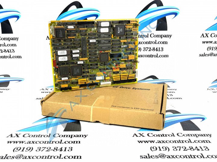
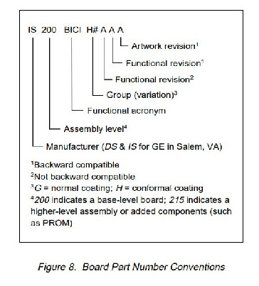
The GE Drive Control Board DS200SDCCG4AEC is the primary controller for the greater Mark V drive assembly. This Drive Control Board may be commonly referred to by its functional acronym of "SDCC." The Mark V Speedtronic series is considered a legacy series, as it mass production of this part has been discontinued by the original manufacturer GE Motors and Industrial Systems. This product is a modified version of the original DS200SDCCG4AEC printed circuit board; and has a three-fold revision history. This DS200SDCCG4AEC PCB also belongs to the relatively-uncommon Mark V Series group 4 product grouping.
Hardware Tips and Specifications
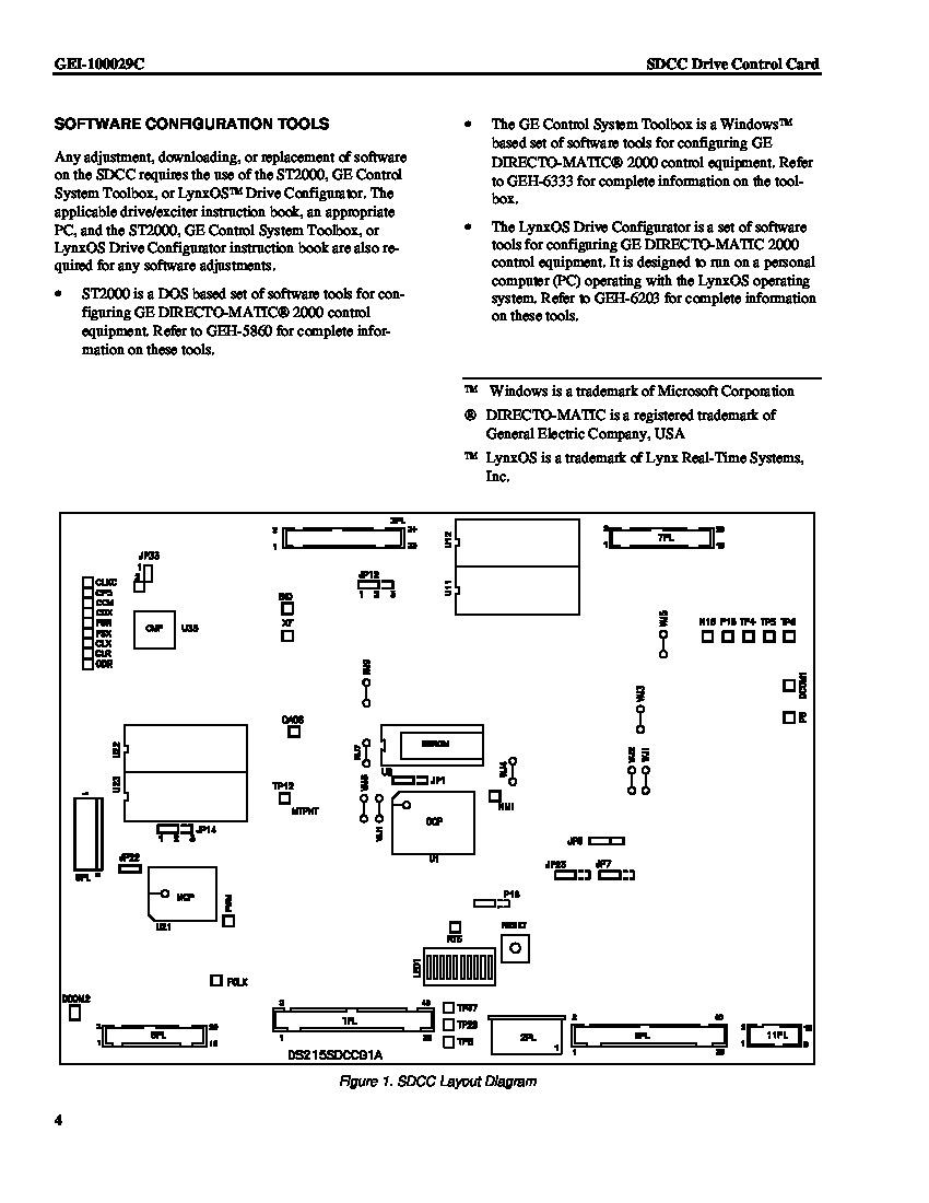
The GE Drive Control Board DS200SDCCG4AEC is populated with 3 microprocessors and RAM that can be accessed by multiple microprocessors at the same time. These microprocessors include:
- A Drive Control Microprocessor or DCP
- A Motor Control Processor or MCP
- A Co-Motor Processor or CMP
The DS200SDCCG4AEC Board's DCP microprocessor is in charge of decoding for chip selects, wait-state generators, a singular interrupt controller, timer/counters, and the assembly's direct memory access. This SDCC Module's Motor Control processor processes fitting motor-focused functions including dc phase control, ac motion control, and ac general purpose drive functions. Finally, the processes that the DS200SDCCG4AEC board's CMP microprocessor handles include any math-intensive control function that the MCP is too simple to process.
The GE Drive Control Board DS200SDCCG4AEC contains all the processing functionality to control the drive. This Control Board can also transmit and receive signals to other boards and devices to perform as described. However, optional cards are available to add extra functionality to the board. The cards are used to add communication functionality to a local area network and provide added signal processing capability. These Cards include the DS215SLCC Communications Card, the 531X306LCC LAN Communications Card, the 531X309SPC Signal Processor Card, and the DS200SPCB Multibridge Signal Processor Card. Descriptions of the various functions of these daughterboard cards can be found online in their original factory-issued instructional manuals.
The DS200SDCCG4AEC is an intuitive Drive Control Board, as it features a series of ten LED indicators on its face plate for function monitoring and fault detection purposes. Fault codes for this SDCC Control Board are either displayed on the indicator in binary coded decimal or binary form, depending on the severity of the fault. Descriptions of the different blinking patterns and BCD positioning pertinent to the DS200SDCCG4AEC's LEDs are available in the correct manual material attached above in the "manuals" tab.
A final highlightable trait of the DS200SDCCG4AEC exists in its set of configurable hardware, which must be applied correctly to ensure normative drive functioning. This hardware includes both a Berg-type manually moveable hardware jumper, labeled by the nomenclature JP, as well as several wire jumpers labeled with the WJ nomenclature. These jumpers, included for both factory and user testing opportunities, have mostly been factory set.
Installation Tips and Specifications
Standoffs are supplied on the GE Drive Control Board DS200SDCCG4AEC to attach the various option cards compatible with this model. Use a screwdriver to attach the cards using the screws that are supplied with the cards. Before attempting removal or replacement of any circuit board, Mark V Series or otherwise, it is of paramount importance to ensure that all power is removed from the face of the PCB, as it carries a certain electrocution risk during installation.
One or more cables are attached from the card to connectors on the board. If you must replace the GE Drive Control Board DS200SDCCG4AEC you must first disconnect the cables from the auxiliary cards, simultaneously using a screwdriver to remove the screws that secure the cards to the board. Keep the screws, cables, and cards together in safe place and ready for use. When you are ready to setup the replacement board, attach the cards to the board and reconnect the cables. Remember to always make use of factory-issue nylon washers to prevent any chafing or stripping of DS200SDCCG4AEC's screws, and that all of the plastic holders positioning the board in place are firmly closed and tightened completely.
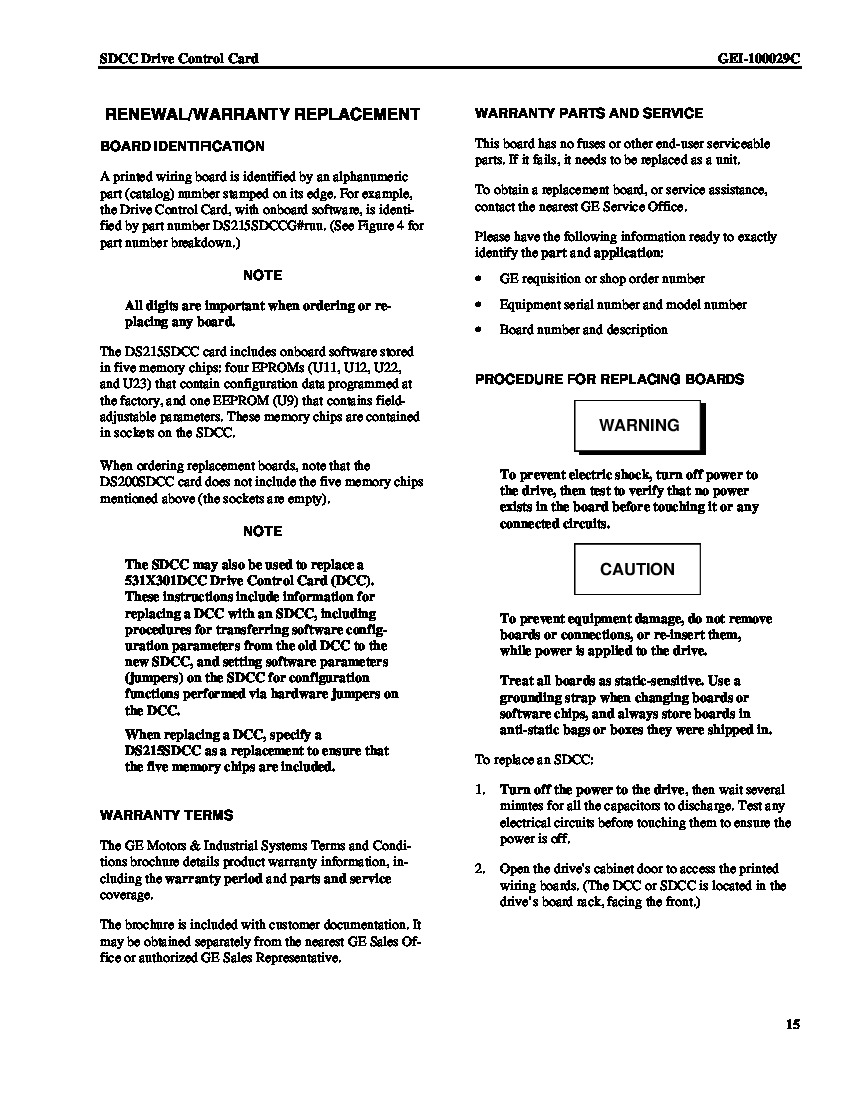
When replacing your DS200SDCCG4AEC module, it is important to remember to also remove the EPROM modules from the defective board. Use your thumb and forefinger to pull the EPROMs from the board and insert them into the connectors on the replacement board. Use one finger to press them gently into the connector.


