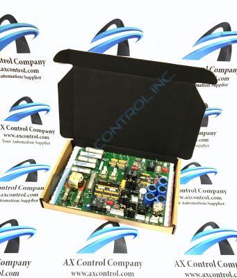
About the DS200SDCIG1
This DS200SDCIG1 printed circuit board product offering was, as mentioned before, originally manufactured for General Electric's Mark V Turbine Control System Series. As made obvious through its full extended series name, the Mark V Series that this DS200SDCIG1 printed circuit board belongs to has specific applications in the control and management systems of wind, gas, or steam turbine control and management systems. This DS200SDCIG1 product offering's greater Mark V Series is additionally definable as one of the final General Electric product series to incorporate their patented Speedtronic control system technology into its range of products. The Speedtronic control system technology seen in this DS200SDCIG1 printed circuit board or PCB for short and its greater Mark V Series was first introduced to the automated industrial landscape along with the rollout of the Mark I Series in the mid to late 1960s. While the Mark V Turbine Control System Series is well-updated in terms of its control system technology, it must be largely considered obsolete, as it has been discontinued for manufacture in the many years following its release and is considered a legacy product series.
Hardware Tips and Specifications
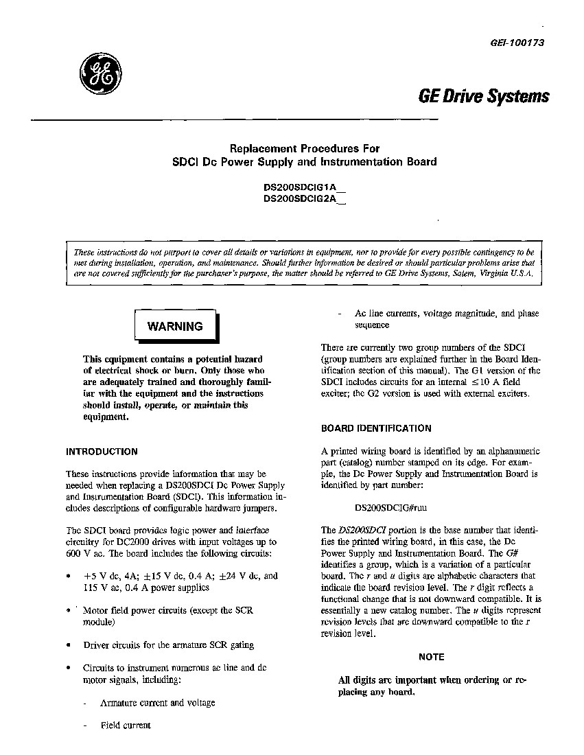
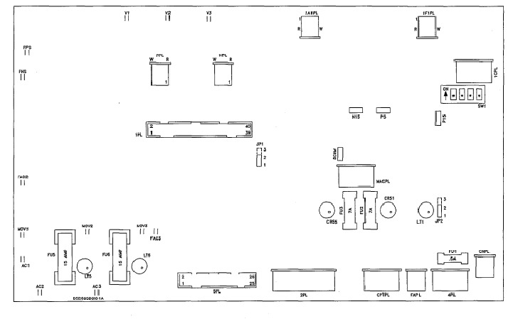
The General Electric DC Power Supply and Instrumentation Board DS200SDCIG1 serves as an interface to DC2000 drives. The need might arise for you to return the DS200SDCIG1 or call for customer support for assistance. One edge of the board has printed on it information that you must have available when you call. Carefully look on the edge of the board for the model number, catalog number, and serial number. Have that information written down before you call. The DS200SDCIG1 contains several fuses that you can replace if needed. Each fuse has an LED indicator associated with it that is lit when the fuse is blown. One fuse is for the 115 V power supply, one fuse is for the positive signal power supply, one is for the negative signal power supply, one is for the 15 amp NRX assembly, and one is for the 10 amp NRX assembly. While the fuses in the assembly of this DS200SDCIG1 product offering are certainly important to identify, so too is its varied selection of adjustable hardware components. As with any hardware component in the assembly of this DS200SDCIG1 Mark V Series printed circuit board device, this DS200SDCIG1 PCB's adjustable hardware inclusions, which exist as two jumpers and a switch, are accompanied by their own factory-printed nomenclature labels, as designated in the DS200SDCIG1 instructional manual attached above. This DS200SDCIG1 PCB's adjustable hardware components include:
- The JP1 MD Control Source Jumper
- The JP2 MA Ac Contactor Drop-Out Time Jumper
- The SW1 Select Ac Line Burdens as a function of Nominal Dc Output Current Switch
Each of the pieces of customizable hardware in this DS200SDCIG1 Mark V Series product offering's assembly has been named through a combination of their specific factory-printed nomenclature labels and their specific specification that they select for in the DS200SDCIG1 Board's greater Mark V Series automated drive assembly. Due to this DS200SDCIG1 product's Mark V Series attribution, it can be assumed that this DS200SDCIG1 PCB's jumpers exist as manually-moveable styles of Berg-type hardware jumpers. Voltage limitation in the assembly of this DS200SDCIG1 Mark V Series product offering is generally handled by its internal assembly's acceptance of a number of Mark V Series-standardized voltage-limiting hardware components, such as rectifiers, capacitors and resistors. It is best practice to allow only trained individuals to service the DS200SDCIG1 board. The individual should be familiar with the equipment. Also the individual should be familiar with the hazards of working with high voltage equipment and understand the steps required to avoid injury and to avoid damage to components and other equipment. If you suspect that the board must be replaced, first disconnect all power to the drive in which it is installed. Then access the board and test it to make sure no electrical current remains in the board. Only then can you touch the board and inspect it. As seen in the DS200SDCIG1 layout attached for your benefit in the manuals tab above, this DS200SDCIG1 device does not include any study metal installation faceplate in its normal Mark V Series assembly; this means that it is not developed specifically for mounting in the Mark V Series' VME Rack mounting assembly as usually is the case.


