About the DS200SDCIG1A
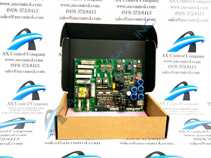
This DS200SDCIG1A Mark V Turbine Control System Series product offering was originally manufactured by General Electric, as discussed briefly above. With that being true, the DS200SDCIG1A PCB's greater Mark V Series has rather obvious applications in both the management and control systems of compatible and popular wind, steam, and gas turbine automated drive assemblies. This DS200SDCIG1A PCB's greater Mark V Series also exists as a now-obsolete legacy product series, as its production and design was canceled in one of the many years following its original conception. With this being true, this DS200SDCIG1A PCB is still well-updated in one respect at least, as it is one of the final General Electric product series to make use of its patented Speedtronic control system technology first introduced alongside the release of the Mark I Series in the mid to late 1960s. This DS200SDCIG1A printed circuit board or PCB for short is functionally-definable as a Dc Power Supply and Instrumentation board, although it does not exist as the original Mark V Series product developed for this specific functional role; that would be the DS200SDCIG1 parent Dc Power Supply and Instrumentation Board missing this DS200SDCIG1A printed circuit board product offering's singular A-rated functional product revision.
Hardware Tips and Specifications
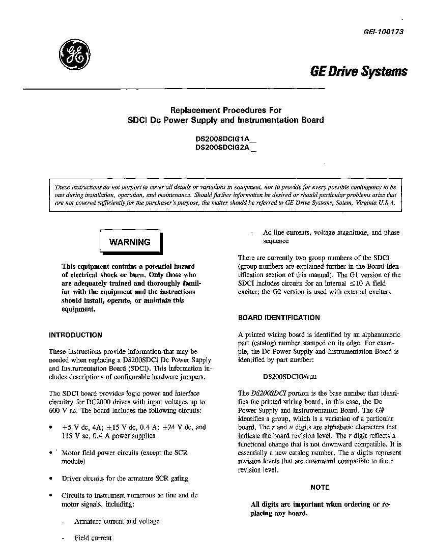
The GE DC Power Supply and Instrumentation Board DS200SDCIG1A serves as an interface to DC2000 drives. Troubleshooting and usability of the board is improved because each fuse has an LED indicator that indicates when the fuse with which it is associated blows. You must complete the following steps to view the board and check for a lit indicator LED light, as revealed in the DS200SDCIG1A Instructional Manual attached above. To begin, open the cabinet in which the board is installed and inspect the board and note any LED lights that are lit. The potential exists for high-voltage being present on the board so do not touch the board or any components around the board. Write down any information about the identifier of the fuse. Then, remove all current from the drive. Open the cabinet and test the board to make sure all power is removed from the board. You might have to allow some time for all power to exit the board to avoid damage. You might be able to inspect the board for wiring errors or a short, depending on which fuse has blown. It might be that the board is defective and must be removed and replaced. When you remove the board for inspection, keep it from touching other boards or devices in the drive. Also avoid touching the panels, cables, or the plastic snaps that hold the board in place. Also, be sure to carefully remove all the cables. Do not pull ribbon cables apart. Instead, hold both connectors with your fingers and disconnect the ribbon cable from the connector. All digits are important when ordering this board. Be sure to order the correct SDCI board for your particular application.
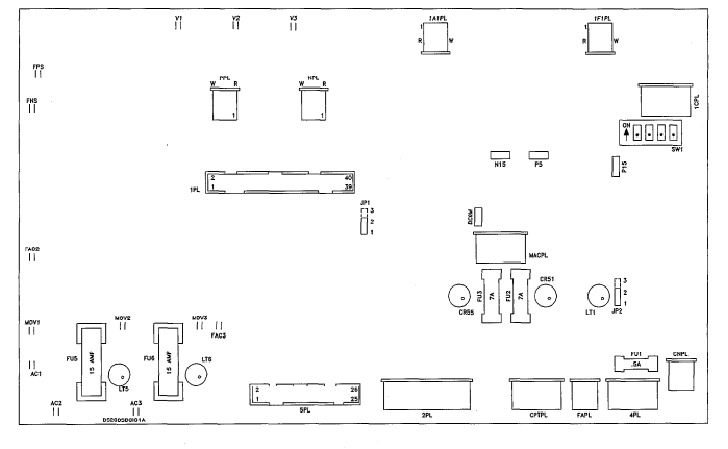
While the various installation and replacement requirements of this DS200SDCIG1A product offering are certainly important to fully understand, so too are this DS200SDCIG1A Mark V Series product's actual hardware components beyond its diagnostic LED indicators. This DS200SDCIG1A PCB is well voltage-regulated product, and this is symbolized well by the elevated number of fuse components made available to its normal Mark V Series assembly. Each of the fuses in the assembly of this DS200SDCIG1A product offering is accompanied by a standard FU1-FU6 factory-printed nomenclature label. Some of this DS200SDCIG1A Dc Power Supply and Instrumentation Board's fuses include the FU1 fuse for 115 V ac power supply brought to 3TB, the FU2 fuse for +24, + 15, and + 5 V dc signal-level power supplies, the FU3 fuse for -24 and -5 V dc signal-level power supplies, the FU5 fuse for internal NRX 10 A field and/or MOV assembly, and finally the FU6 fuse for internal NRX IO A field and/or MOV assembly. All of the above-listed fuses in the assembly of this DS200SDCIG1A printed circuit board have been named through a basic combination of their factory-printed nomenclature labels and their specific functionality in terms of the Mark V Series automated drive assembly and the smaller DS200SDCIG1A Board. Three pieces of customizable hardware have been made available to this DS200SDCIG1A PCB as well. These exist as both hardware jumper and switch components. This DS200SDCIG1A PCB's customizable hardware includes:
- The JP1 MD control source jumper
- The JP2 MA ac contactor drop-out time jumper
- The SW1 Select ac line burdens as a function of nominal output current switch


