About the DS200SDCIG1ABA
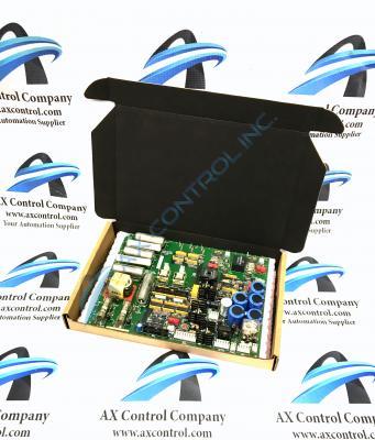
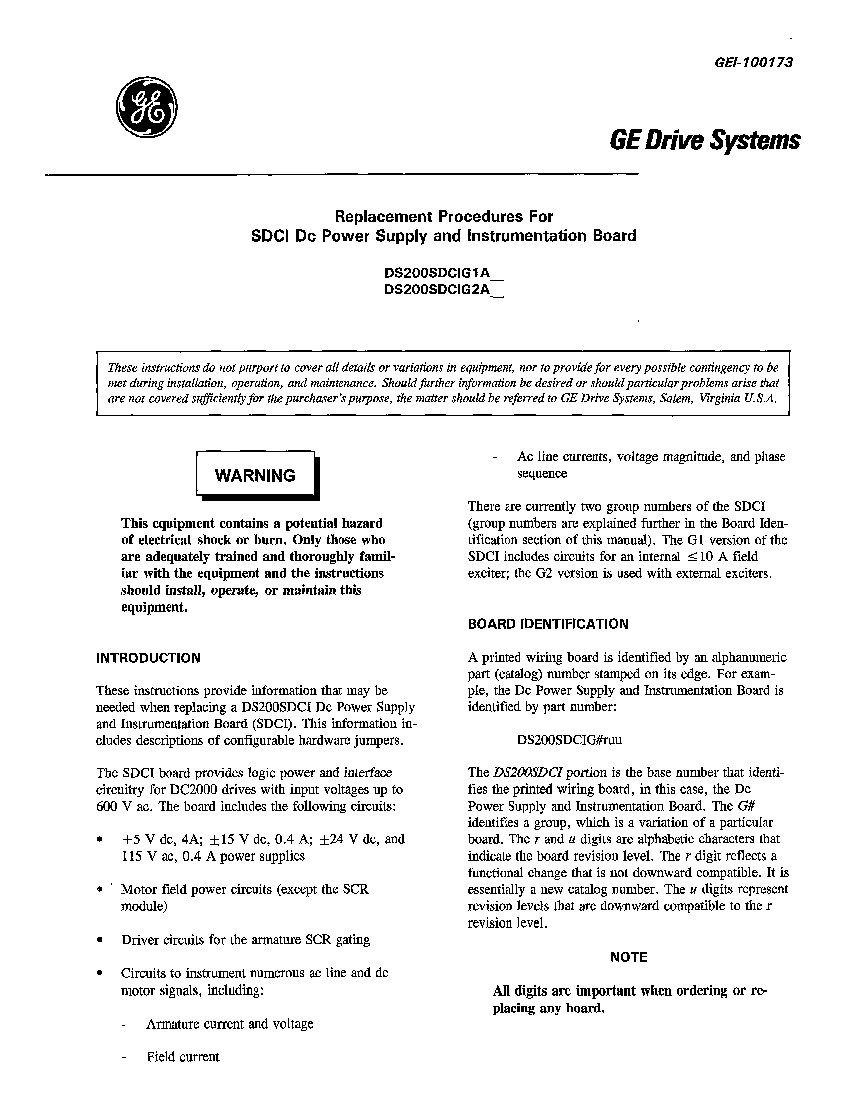
The GE DC Power Supply and Instrumentation Board DS200SDCIG1ABA serves as an interface to DC2000 drives within its greater Mark V Turbine Control System Series. The Mark V Series that this DS200SDCIG1ABA PCB belongs to has specific applications in the control and management systems of wind, steam, and gas turbine automated drive assemblies. The Mark V Turbine Control System Series that this DS200SDCIG1ABA PCB belongs to is also noted as one of the final General Electric product series to make use of the patented Speedtronic control system technology in its various product offerings.
While this DS200SDCIG1ABA printed circuit board or PCB for short is definable as a DC Power Supply and Instrumentation Board, it is not the original Mark V Series product of this functionality; that would be the DS200SDCIG1ABA printed circuit board missing this DS200SDCIG1ABA PCB's three-fold revision history.
Hardware Tips and Specifications
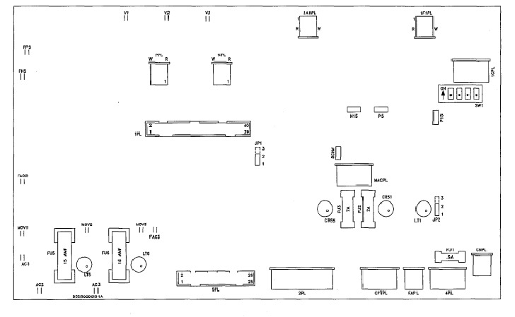
This DS200SDCIG1ABA printed circuit board gains functionality as a DC Power Supply and Instrumentation Board thanks to its adoption of several unique and important hardware components and component specifications. For starters, this DS200SDCIG1ABA PCB's assembly features many Mark V Series-standardized voltage-limiting hardware components, including various rectifiers, diodes, capacitors, and integrated circuits. On top of this, the entirety of DS200SDCIG1ABA hardware components and set specifications on its base circuit board are well-protected by its thick, rudimentary style of normal PCB coating, which envelops and protects individual DS200SDCIG1ABA board hardware components on a functional priority basis. Multiple fuses and jumpers are additionally made available to this DS200SDCIG1ABA product's assembly; each with their own instructional manual-introduced application. The fuses in this DS200SDCIG1ABA printed circuit board's assembly include:
- The FU1 115 V Ac Power Fuse
- The FU2 Dc Signal-Level Power Supplies Fuse
- The FU3 Dc Signal-Level Power Supplies Fuse
- The FU5 Internal NRX 10 A Field/MOV Assembly Fuse
- The FU6 Internal NRX 10 A Field/MOV Assembly Fuse
All of these listed fuses in the assembly of the DS200SDCIG1ABA Dc Power Supply and Instrumentation Board have been named through a combination of their originally-intended functionality and their factory-printed nomenclatures. Three total jumpers are made available to the assembly of this DS200SDCIG1ABA printed circuit board in the JP1 MD Control Source Jumper, the JP2 MA AC contactor drop-out time jumper, and the SW1 select AC line CT burdens as a function of nominal DC output current Jumper. As with the fuses listed above, these jumpers in the DS200SDCIG1ABA printed circuit board's internal assembly are named through a combination of their individual labels and their specific functional selection for the greater DS200SDCIG1ABA board and Mark V Series automated drive. The jumpers and fuses available to the assembly of this DS200SDCIG1ABA product offering are not physically grouped together on the DS200SDCIG1ABA PCB's base board; instead being applied as needed functionally.
Service and periodic maintenance must be performed on the DS200SDCIG1ABA only by qualified individuals. That is, don’t attempt to remove and replace the board yourself because of the high-voltage present in the drive and the board. You could unknowingly damage the board by allowing the board to touch components in the drive cabinet or damage cables by using an incorrect method to remove the cables. There is one troubleshooting task you can perform yourself. You can open the cabinet and view the LED indicators on the board with power present in the drive and board. If an LED indicator is lit it indicates that the fuse associated with the LED is blown. However, you must not touch the board or any components in the drive. If you see a blown fuse and you want to remove the board, you must perform the following procedure. Not only must you switch off the drive but you have to remove the fuses on the 3-phase power supplies. Also make sure to remove the auxiliary power supply as well. Wait several minutes for power to exit the board. Before you proceed, use a tester device to verify that there is no power present in the board.


