DS200SDCIG1AEB

    Varying star amount pictures Varying star amount pictures Varying star amount pictures Varying star amount pictures Varying star amount pictures
  • 4.94 (17)
  • Click a star to rate this product
    Varying star amount pictures Varying star amount pictures Varying star amount pictures Varying star amount pictures Varying star amount pictures
  • 4.94 (17)
  • Click a star to rate this product
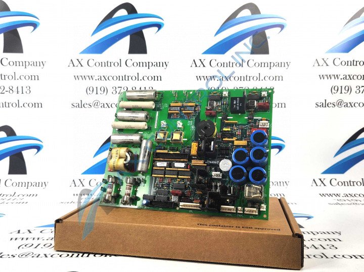
Model Number DS200SDCIG1AEB is a DC Power Supply and Instrumentation Board produced by General Electric for the Mark V series.

AVAILABILITY:

IN STOCK
SHIPS TODAY

Sell Surplus: Have a DS200SDCIG1AEB to sell? Sell Now
Exchange Credit: Learn more about our exchange credit program
  • Part Number: DS200SDCIG1AEB
  • SKU: DS200SDCIG1AEBGBTC
  • Manufacturer: GE Boards & Turbine Control
  • Series: Mark V DS200

DS200SDCIG1AEB Technical Specifications

Part Number DS200SDCIG1AEB
Series Mark V
Manufacturer GE General Electric
Instruction Manual GEI-100173
Product Type SDCI DC Power Supply and Instrumentation Board
Functional Acronym/Abbreviation SDCI
Group Revision G1
Field Exciter Value Less Than or Equal to 10 A

About the DS200SDCIG1AEB

This DS200SDCIG1AEB General Electric printed circuit board is better-known by its official functional description as a DC Power Supply and Instrumentation Board that was originally manufactured for the Mark V Series of Turbine Control Systems, as described above. The Mark V Series that this DS200SDCIG1AEB DC Power Supply and Instrumentation Board belongs to is one of the more recent product series released with General Electric's patented Speedtronic technology-powered control system, which began with the Mark I Series released in the late 1960's by GE. This DS200SDCIG1AEB General Electric printed circuit board or PCB for short is not classifiable as the original DC Power Supply and Instrumentation Board that was released for the Mark V Turbine Control System Series; that would be the DS200SDCIG1 parent printed circuit board missing this DS200SDCIG1AEB product's full range of three significant product revisions.

Hardware Tips and Specifications 

The GE DC Power Supply and Instrumentation Board DS200SDCIG1AEB serves as an interface to DC2000 drives, and given this specific Mark V Series intended functionality, necessitates its own series of hardware component inclusions and specifications in its internal and external assembly. The DS200SDCIG1AEB is populated with 5 fuses that serve to protect the board from damage. If a power overload condition occurs, a fuse might blow to protect components from being damaged. A valuable feature of this DS200SDCIG1AEB product is that if a fuse blows, you can inspect the LED lights on the board and confirm that a problem with the board has occurred.  You can refer to the information that came with the board and determine the possible reasons for the fuse to blow. This DS200SDCIG1AEB model is just one of two group revisions within the Mark V Series. The DS200SDCIG1AEB model is part of the G1 group and will have an internal field exciter supply less than or equal to 10 A.

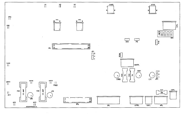
Three significant pieces of adjustable hardware exist in the assembly of this DS200SDCIG1AEB DC Power Supply and Instrumentation Board are available for product customization purposes. Each of the three manually-moveable hardware jumpers in the internal configuration of this SDCI-abbreviated product offering is accompanied by its own factory-printed nomenclature, in typical General Electric fashion. The jumpers in the assembly of this DS200SDCIG1AEB product include:

  • The JP1 MD Control Source-Selecting Jumper
  • The JP2 ac Contactor Drop-Out Time-Selecting Jumper
  • The SW1 ac Line Burdens Nominal DC Output Current-Selecting Jumper

All three of these above manually-moveable hardware jumpers are named by a combination of their designated factory-printed label designator and their function pertinent to the DS200SDCIG1AEB DC Power Supply and Instrumentation Board. For more information on the specific applications of each jumper included in this DS200SDCIG1AEB PCB's internal assembly, please access the DS200SDCIG1AEB instructional manual available in the manuals tab above. The normal style of PCB coating that has been applied to this DS200SDCIG1AEB printed circuit board should provide the bulk of its hardware elements with basic insulation and daily wear and tear protection.

Frequently Asked Questions about DS200SDCIG1AEB

What power supply circuits does DS200SDCIG1AEB have circuits for?
DS200SDCIG1AEB has circuits for power supplies: +5 VDC, 4A; +/-15 VDC, 0.4A; +/-24 VDC and 115 VAC, 0.4A.
What is covered in the manual for DS200SDCIG1AEB?
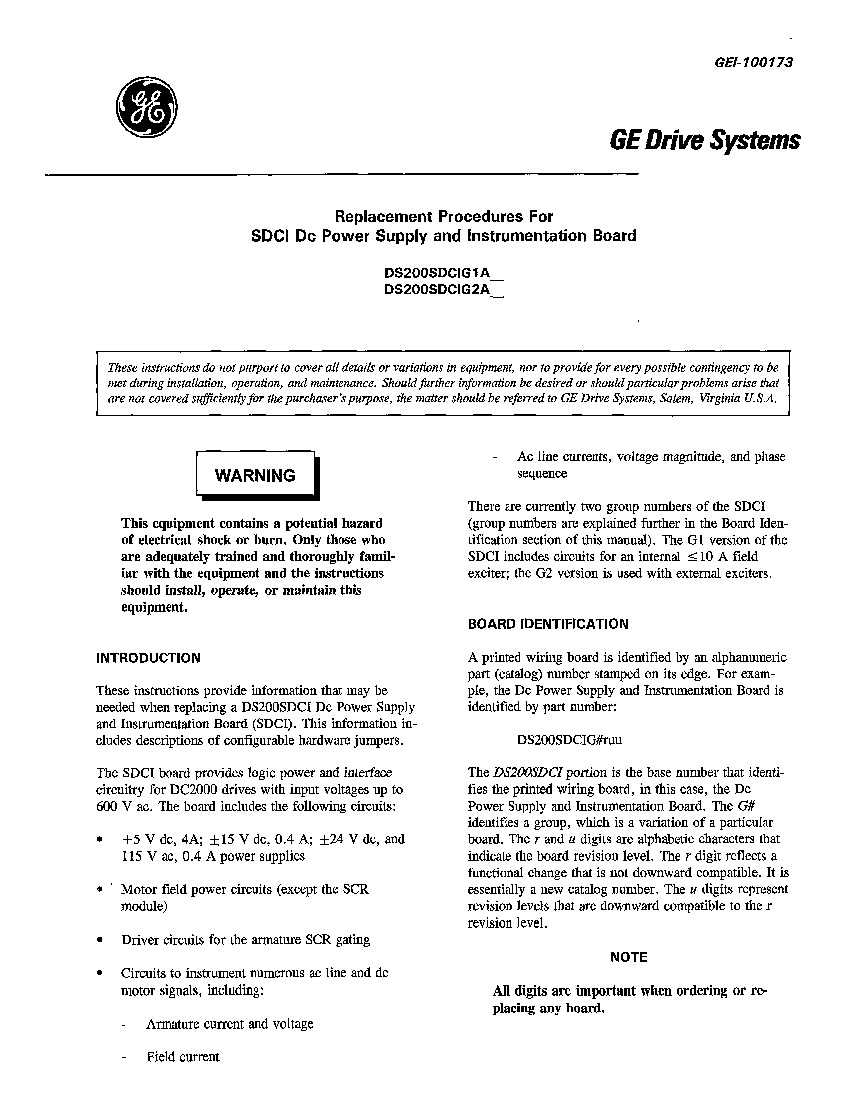
The manual for DS200SDCIG1AEB, Manual GEI-100173, the GE Drive Systems Replacement Procedures for SDCI DC Power Supply and Instrumentation Board Manual, provides instructions on the information needed when replacing a DS200SDCIG1AEB but also covers some other aspects of DS200SDCIG1AEB such as circuitry, jumpers, hardware, etc. The manual for DS200SDCIG1AEB does not cover everything about DS200SDCIG1AEB, and the manual should not be intended to provide every possible contingency during installation, operation, and maintenance of DS200SDCIG1AEB, but the manual will help greatly with DS200SDCIG1AEB.
What is fuse \"FU3\" used for on DS200SDCIG1AEB?
Fuse "FU3" on DS200SDCIG1AEB is the fuse for -24 and -5 VDC signal-level power supplies. If fuse "FU3" on DS200SDCIG1AEB is blown, the programmer is unable to display fault messages, but LED CR55 will be illuminated when control power is applied to the drive. When the "FU3" fuse is blown on DS200SDCIG1AEB, it's usually because of an accidental short of -24V, either while probing or due to a wiring error at the terminal board.
Which circuits on DS200SDCIG1AEB connect to AC line and DC motor signals?
Circuits to instrument numerous AC line and DC motor signals on DS200SDCIG1AEB include armature current and voltage, field current, AC line currents, voltage magnitude, and phase sequence.

Reviews For DS200SDCIG1AEB

Internal Review
(5.0)

One of the best features of the DS200SDCIG1AEB model is that not only can it be used with Mark V systems, but it can also be used with DC2000 drives. When used with the DC2000 drives it will provide interface circuitry and logic power to the drives with input voltages up to 600 VAC. For more circuitry information refer to the attached GE Manual. This DS200SDCIG1AEB DC Power Supply and Instrumentation Board makes use of a seldom-seen E-rated secondary functional product revision. - AX Control Lead Technician

Repair Services For DS200SDCIG1AEB

Type Lead Time Price Action
Repair Service 1-2 weeks $985

Our highly skilled technicians can repair your DS200SDCIG1AEB. All of our repairs come with a 3 Year AX Control Warranty. Please contact us for additional information about our repair process. To receive the repair pricing and lead time listed above please process your repair order via our website. The following repair options may be available upon request:

  • 48-72hr Rush Repair
  • Detailed Repair Reports
  • AX Control Certificate of Warranty

AX Control Warranty Info

All products we sell are backed by our unparalleled warranty. A warranty certificate will be provided with your order upon request.
All PLCs, HMIs, and Turbine Control Boards: 3 Years
All AC/DC and Servo Drives: 2 Years
All Motors: 1 Year
Learn More