In Stock
DS200SDCIG2 GENERAL ELECTRIC POWER SUPPLY BOARD | Image
3 year warranty

DS200SDCIG2 GENERAL ELECTRIC POWER SUPPLY BOARD | Image

DS200SDCIG2

    Varying star amount pictures Varying star amount pictures Varying star amount pictures Varying star amount pictures Varying star amount pictures
  • 4.94 (17)
  • Click a star to rate this product
    Varying star amount pictures Varying star amount pictures Varying star amount pictures Varying star amount pictures Varying star amount pictures
  • 4.94 (17)
  • Click a star to rate this product
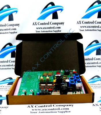
The DS200SDCIG2 Power Supply/Instrumentation Board was designed for the Mark V Turbine Control Series of General Electric.

AVAILABILITY:

IN STOCK
SHIPS IN 3-5 DAYS

Sell Surplus: Have a DS200SDCIG2 to sell? Sell Now
Exchange Credit: Learn more about our exchange credit program
  • Part Number: DS200SDCIG2
  • SKU: DS200SDCIG2GBTC
  • Manufacturer: GE Boards & Turbine Control
  • Series: Mark V DS200

DS200SDCIG2 Technical Specifications

Manufacturer GE General Electric
Series Mark V
Part Number DS200SDCIG2
Functional Description SDCI DC Power Supply and Instrumentation Board
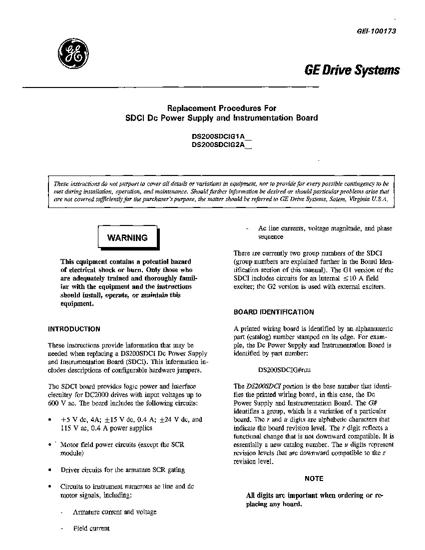
Instruction Manual GEI-100173
Functional Acronym SDCI
PCB Coating Normal Coating

Product Description

The General Electric Direct Current Power Supply and Instrumentation Board DS200SDCIG2 serves as an interface to DC2000 drives. This DS200SDCIG2 Power Supply and Instrumentation Board, while specifically designed for the DC2000 subseries, is additionally considered a product existing within the more general Mark V Series of General Electric printed circuit boards, as evidenced by its inclusion in pertinent Mark V Series instructional manuals and its possession of a General Electric alphanumeric product number. This DS200SDCIG2 Power Supply and Instrumentation Board actually does exists as the original product manufactured for the Mark V and DS2000 Series, as it does not appear to have been revised at all, functionally or not.

Hardware Tips and Specifications

There are multiple fuses on the DS200SDCIG2 that help protect the components of the board from current overload, accidental electrical shorts, defective MOV assemblies, and defective SCR packages. A blown fuse might indicate that the  board is defective. One feature to assist with troubleshooting is that each fuse has a LED light that is lit when the fuse is blown. That helps with problem identification.  However, because the LED are only visible if power is supplied to the board, safety procedures must be followed to view the LEDs.

The DS200SDCIG2 is installed behind another board in the drive cabinet so several steps are involved in viewing the LEDs in this PCB's assembly for diagnostic testing purposes, as described in original Mark V Series instructional manual materials. First, turn off the drive to initiate a controlled power down of the drive, before removing the fuses from the power supplies to remove all power. The next step in this process would be to open the cabinet and tilt forward the first board in the cabinet. You now have a clear view of the DS200SDCIG2; apply current to the drive and perform a restart procedure. It is now possible to open the cabinet and inspect the board for lit LED lights. 

While understanding the fragile assembly and diagnostic LED indicator system specific to this DS200SDCIG2 Power Supply and Instrumentation Board is certainly important, so too is achieving an understanding of this PCB's specific hardware inclusions. This DS200SDCIG2 Mark V Series printed circuit board includes three total manually-moveable hardware jumper switches in its assembly for customization purposes; the JP1-labeled jumper selects this device's MD control source, the JP2-labeled jumper selects MA ac contactor drop-out time, and the SW1-labeled jumper switch is responsible for the selection of Select ac line CT burdens.

Frequently Asked Questions about DS200SDCIG2

How do I replace a DS200SDCIG2?
To replace a DS200SDCIG2, it is best to look at the manual for DS200SDCIG2 - Manual GEI-100173- which is a manual specific to replacement procedures for DS200SDCIG2. On the second page of the manual for DS200SDCIG2, there is a section on the procedure for replacing boards. Follow this procedure in the manual carefully in order to replace DS200SDCIG2 properly. The manual provides an 8-step procedure for replacing DS200SDCIG2.
What is fuse "FU1" used for on DS200SDCIG2?
Fuse "FU1" on DS200SDCIG2 is the fuse for 115 VAC power supply brought to 3TB. "FU1" on DS200SDCIG2 protects the 115 VAC power supplied for customer use.
Where can I find the manual for DS200SDCIG2?
We'd be happy to send you the manual for DS200SDCIG2. The manual for DS200SDCIG2 is Manual GEI-100173. This manual is the GE Drive Systems Replacement Procedures for SDCI DC Power Supply and Instrumentation Board Manual and is the specific manual for DS200SDCIG2.
What type of jumpers does DS200SDCIG2 use?
DS200SDCIG2 uses Berg-type or manually moveable jumpers identified by a JP nomenclature.

Reviews For DS200SDCIG2

Internal Review
(5.0)

This DS200SDCIG2 Power Supply and Instrumentation Board is a Mark V Series product offering that exists as the original product released by General Electric, as mentioned above. With this being true, this unrevised printed circuit board is still supported through its strong customization features, including its series of manually-movable hardware jumpers. The LED diagnostic indicators available in the assembly of this DS200SDCIG2 PCB are also a benefit, although to be accessed a circuit board must be removed from the Mark V drive assembly. - AX Control Lead Technician

Repair Services For DS200SDCIG2

Type Lead Time Price Action
Repair Service 1-2 weeks $915

Our highly skilled technicians can repair your DS200SDCIG2. All of our repairs come with a 3 Year AX Control Warranty. Please contact us for additional information about our repair process. To receive the repair pricing and lead time listed above please process your repair order via our website. The following repair options may be available upon request:

  • 48-72hr Rush Repair
  • Detailed Repair Reports
  • AX Control Certificate of Warranty

AX Control Warranty Info

All products we sell are backed by our unparalleled warranty. A warranty certificate will be provided with your order upon request.
All PLCs, HMIs, and Turbine Control Boards: 3 Years
All AC/DC and Servo Drives: 2 Years
All Motors: 1 Year
Learn More

DS200SDCIG2 Manuals, White Papers, Data Sheets, and Troubleshooting