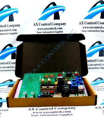
Frequently Asked Questions about DS200SDCIG2A
What circuits are included on DS200SDCIG2A?
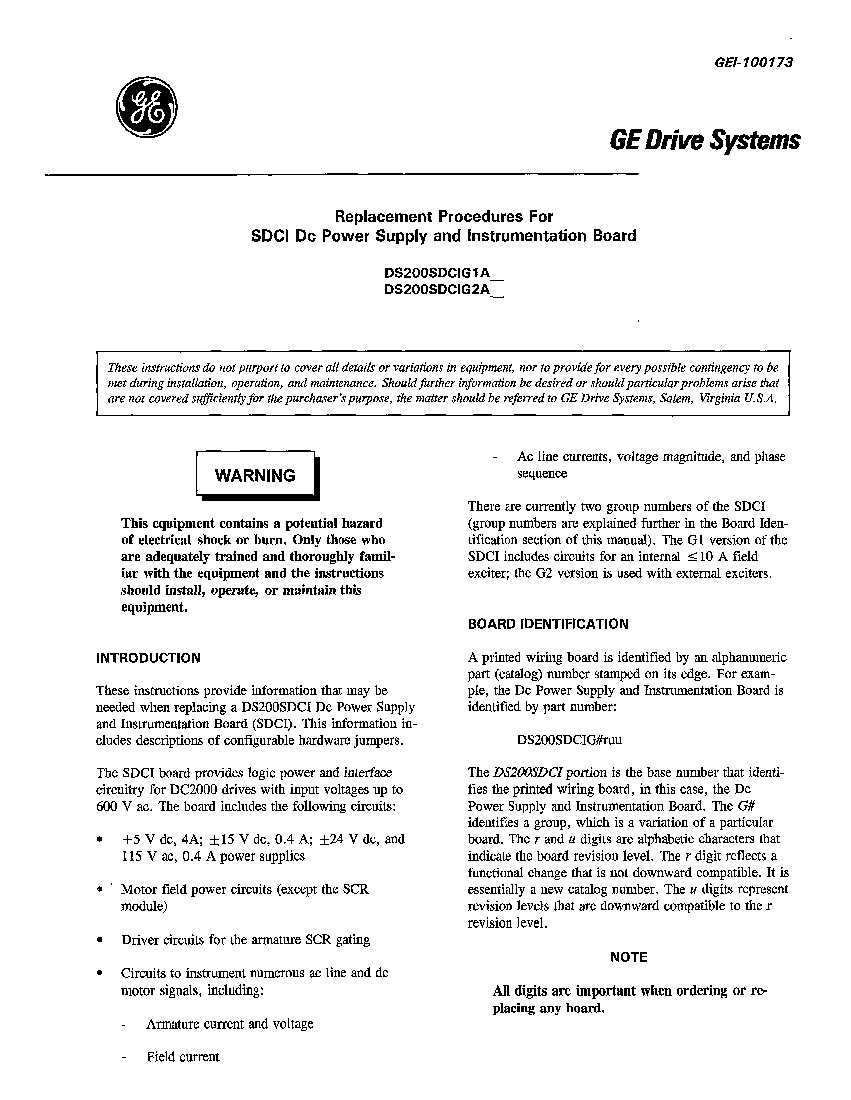
Included on DS200SDCIG2A are circuits for: +5 VDC, 4A; +/-15 VDC, 0.4A; +/-24 VDC and 115 VAC, 0.4A power supplies, motor power field circuits, driver circuits for the armature SCR module, and circuits to instrument numerous AC line and DC motor signals.
What is DS200SDCIG2A used for?
DS200SDCIG2A is used to provide logic power and interface circuitry to DC2000 drives with input voltages up to 600 VAC.
What is included in the manual for DS200SDCIG2A?
The manual for DS200SDCIG2A is the GE Drive Systems Replacement Procedures for SDCI DC Power Supply and Instrumentation Board Manual - Manual GEI-100173. This manual does not include all insllation, operation, and maintenance details for DS200SDCIG2A as the manual is mostly about replacing DS200SDCIG2A, but the manual includes an introduction, board identification for DS200SDCIG2A, procedure for replacing DS200SDCIG2A, fuses on DS200SDCIG2A, hardware adjustments for DS200SDCIG2A, and jumpers on DS200SDCIG2A. For a copy of the manual for DS200SDCIG2A, request Manual GEI-100173.
What power supplies is fuse FU3 used for on DS200SDCIG2A?
Fuse "FU3" on DS200SDCIG2A is the fuse for -24 and -5 VDC signal-level power supplies. This fuse on DS200SDCIG2A is 7 A, 2 AG.


