About the DS200SDCIG2ABA
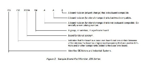
The GE Drive Systems Mark V Series DC Power Supply and Instrumentation Board model DS200SDCIG2ABA provides essential power supply and instrumentation functions for industrial applications. With its precise measurement capabilities, reliable power supply outputs, and robust communication interfaces, it ensures accurate control and monitoring of electrical systems while incorporating necessary protection and diagnostic features for optimal performance, reliability, and flexibility in powering different devices. This "SDCI" board has a three-fold revision history; including a functional revision 1 rated at A, a functional revision 2 at a B rating and an artwork revision sitting at a A grade. The Mark V Series that this DS200SDCIG2ABA product offering belongs to has to be considered a legacy General Electric product series, as it was eventually discontinued in the many years following its initial release due to obsolescence.
Hardware Tips and Specifications
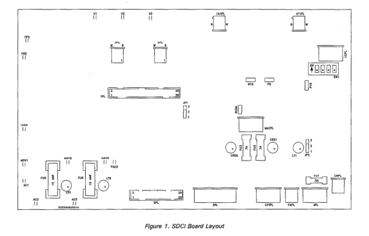
Circuits are not the only component of note visible on the face plate of the DS200SDCIG2ABA. This model of General Electric Legacy Series PCB comes standard with a number of fuses for additional circuit board protection. These fuses, accompanied by their corresponding LED indicators, are labeled FU1 through FU6 on the PCB. This DS200SDCIG2ABA product, often abbreviated simply to SDCI, comes with an additional number of adjustable hardware features. The primary piece of adjustable hardware accessible on the SDCI board is its Berg-type manually movable hardware jumpers. Labeled with handy nomenclatures including JP, these jumpers are used for manufacturing customer or test options. The positioning of these jumpers, which include JP1, JP2, and SW1-labelled jumpers, is revealed below in the embedded SDCI Board Layout diagram sourced from this product's instruction manual GEI-10073.
Installation Tips and Specifications
The DS200SDCIG2ABA is a high-voltage style of drive assembly PCB, and as such; demands respect and caution during installation. This product, as defined in manual GEI-10073, has numerous specifications for its installation process that encourage safety and long-lasting drive use. Potentially lethal voltages can be present on the DS200SDCIG2ABA board, even after rest, so power should always be turned off to the PCB prior to attempting installation or replacement. When properly inserted into the greater drive assembly, this SDCI-abbreviated board should be positioned behind the corresponding SDCC board. To expose the SDCI, the module installer must disengage a series of locks on either cabinet, before lifting the SDCC module to tilt it forward. After this, the next step is to gently remove any ribbon cables or pull tab-connected cables, adhering to specific cable sensitivities as you go along. The SDCI board should be held in place through use of a series of detachable plastic snaps. Remove these snaps, and replacement of the new board should be possible. Ensure during installation that all components on the base plate of the DS200SDCIG2ABA are in the correct position, as with the previous defective board, and that all connector cables are properly seated.


