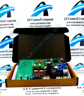
About the DS200SDCIG2AEB
This DS200SDCIG2AEB printed circuit board product offering, as mentioned just above, was originally manufactured for the Mark V Turbine Control System Series. The rather self-explanatory Mark V Series that this DS200SDCIG2AEB printed circuit board or PCB for short belongs to has specific applications in the management and control systems of popular and compatible wind, steam, and gas turbine automated drive assemblies, although it has to be described as a now-obsolete legacy product series given its eventual manufacturing discontinuation that was carried out in the time following its initial Mark series rollout. This DS200SDCIG2AEB PCB's greater Mark V Series is no slouch on the greater automated industrial marketplace, however, as it is one of the final-developed General Electric Mark product series to make use of the patented Speedtronic control system technology across a swathe of its various offerings; including this DS200SDCIG2AEB product. This DS200SDCIG2AEB PCB, while definable as a Power Supply and Instrumentation Board in its own right, is not the originally-developed product of this specific Mark V Series functionality; that would be the DS200SDCIG2 parent printed circuit board missing this DS200SDCIG2AEB Device's three significant product revisions.
Hardware Tips and Specifications
The GE DC Power Supply and Instrumentation Board DS200SDCIG2AEB serves as an interface to DC2000 drives. The DS200SDCIG2AEB is a static-sensitive device and care must be taken when touching, maintaining, and installing the device. Static electricity can accumulate on the board through the air, persons touching the device, and when the device comes in contact with other device and structures. The static electricity can damage sensitive components on the board and lead the board to being unusable. If you plan to maintain the board, place the board on a flat clean surface and wear a grounding strap before touching the board. The grounding strap will prevent static electricity from accumulating. Walking and touching items can cause static electricity to accumulate so it is best practice to not move too much before you work with the board. When you do handle the board only hold it by the edges and never touch the solder points or the components. Just before you are ready to install it remove it from the package and touch it to a unpainted metal surface to drain off any static. Only then is it safe to install the replacement board. If you have to put down the board after removing it from the bag, only place it on top of the empty static-protective bag. The capacitors on the DS200SDCIG2AEB can store high-voltage current even after the current is removed, so it is important to test the board for current before you touch it, so as to prevent electrical burns and shocks.
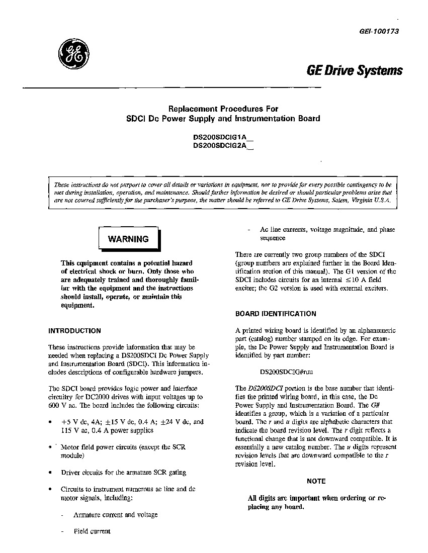
While this DS200SDCIG2AEB printed circuit board's various installation and usage procedures are certainly important to follow, their presence on the DS200SDCIG2AEB personalized product page here is primarily reminiscent of this DS200SDCIG2AEB device's lack of available original instructional manual materials that is true due to its obsolete legacy product series status. Luckily for our sake, this DS200SDCIG2AEB PCB was developed by General Electric, and formulated alongside its own DS200SDCIG2AEB functional product number designed to convey various crucial DS200SDCIG2AEB Board hardware details in a series of consecutive functional naming segments. For example, the DS200SDCIG2AEB functional product number starts off with the dual-functional DS200 series tag describing this DS200SDCIG2AEB Device's normal Mark V Series assembly as well as its domestic original manufacture location. Some of the other information revealed by this DS200SDCIG2AEB PCB's functional product number includes its SDCI functional product acronym, its group 2 Mark V Series product grouping, and finally its A, E, and B-rated significant product revisions. Luckily for us, existing Mark V Series Power Supply and Instrumentation Board manuals describe the three pieces of hardware adjustable in the normal assembly of this DS200SDCIG2AEB product as follows:
- The JP1 Control Source Jumper
- The JP2 MA Contactor Drop-out Time Jumper
- The SW1 Select Ac Line as as Function of Nominal Dc Output Current Switch


