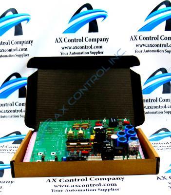
About the DS200SDCIG2AGB
As identified briefly in this DS200SDCIG2AGB product offering's product description inserted above, this DS200SDCIG2AGB printed circuit board was originally manufactured by General Electric, specifically for placement in the Mark V Turbine Control System Series. A rather self-explanatory General Electric product series; the Mark V Series that this DS200SDCIG2AGB PCB belongs to has specific applications in the management and control systems of popular and compatible wind, steam, and gas turbine automated drive assemblies. With this being true, this DS200SDCIG2AGB product's greater Mark V Series has to be considered wholly obsolete, as its manufactured ceased in one of the many years past its original GE product series release due to a manufacturer-identified series functional obsolescence. While generally obsolete, this DS200SDCIG2AGB product offering's Mark V product series is still something of a highly-acclaimed General Electric Mark product series on the larger automated industrial marketplace, as it exists as one of the final-developed product series to make use of the patented Speedtronic control system technology. This DS200SDCIG2AGB printed circuit board is not the originally-developed PCB of its specific Mark V Series functionality; that would be the DS200SDCIG2 parent PCB missing this DS200SDCIG2AGB device's three significant product revisions.
Hardware Tips and Specifications
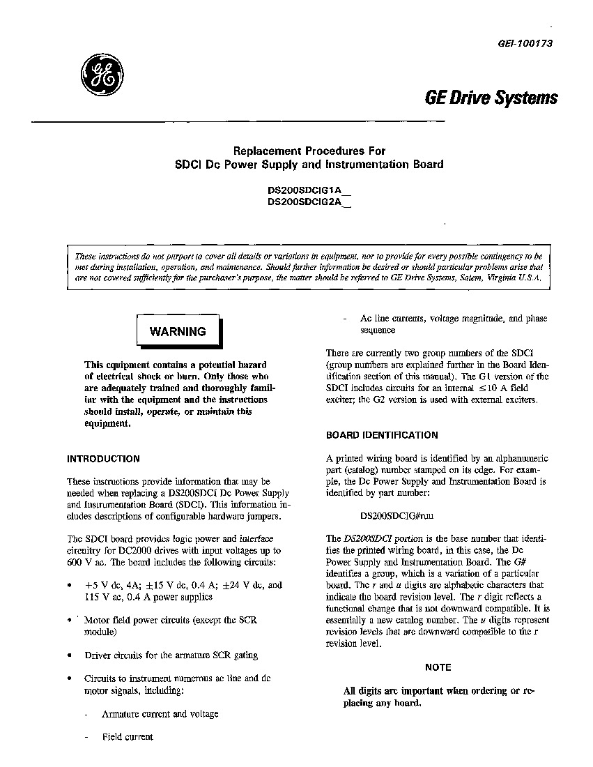
The GE DC Power Supply and Instrumentation Board DS200SDCIG2AGB serves as an interface to DC2000 drives; to achieve this specific Mark V Series functionality, it incorporates several specialized hardware components and component specifications into its normal Mark V Series assembly. To help make sure you have received the correct board, it is best practice to make sure the model number listed on the label on the outside of the box matches the model number and catalog number printed on the edge of the board. You can remove the board from the static-protective package and place the board on top of the bag. Then, inspect the board until you find the identifying information. Write it down for future use. Then, return the board to the static-protective package. In terms of its voltage regulation and protections, this DS200SDCIG2AGB Device's voltage suppression strategy is encouraged by its internal assembly's acceptance of a specific series of voltage-limiting hardware components standardized to the Mark V Series; including various styles of resistors, capacitors, diodes, and specialized integrated circuits. On top of these components, the normal Mark V Series assembly of this DS200SDCIG2AGB product offering is populated by three unique pieces of hardware; two jumper components and a singular switch component. The adjustable hardware components in this DS200SDCIG2AGB PCB's assembly include its:
- JP1 MD Control Source Jumper
- JP2 MA Ac Contactor Drop-out Time Jumper
- The SW1 Select Ac Line CT Burdens as a Function of Nominal Dc Output Current Switch
All of the adjustable hardware components in this DS200SDCIG2AGB device's assembly have been named through a formulated combination of their factory-printed nomenclature labels and the specific value or application that they were developed to select for. The steps for replacing the DS200SDCIG2AGB board should be performed by an experienced and knowledgeable servicer. The drive and board carry high-voltage energy and great care should be taken. First, turn off the current to the drive. Refer to the information that came with the drive to understand how to completely remove all current. Test all circuits before you proceed to verify that all current is off. Wait a few seconds for all current to exit the board. The board needs time for current to exit the capacitors that store current during operation. Open the cabinet that contains the printed circuit boards. Another board is installed in front of the DS200SDCIG2AGB. You can tilt that board forward to expose the DS200SDCIG2AGB. Remove all cables from the board and be careful not the damage the cables. Also, if necessary label the cables so that you can easily reconnect the cables on the replacement board.


