About the DS200SDCIGIAHB
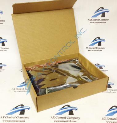
The GE DC Power Supply and Instrumentation Board DS200SDCIGIAHB serves as an interface board to the DC2000 drives. The DC2000 drives series is a subseries of this General Electric product's greater Mark V Turbine Control System Series, and exists as a legacy product series that has been discontinued for manufacture in the years following its initial release. This specific DS200SDCIGIAHB Power Supply and Instrumentation Board is not the originally-developed product of its specific functionality to appear in a Mark V legacy series; that would be the DS200SDCIGI parent printed circuit board missing all three of this DS200SDCIGIAHB PCB's significant product revisions. While the assembly of this DS200SDCIGIAHB Mark V Series product has been altered through revisions, it is still considered to exist as the normal Mark V Series assembly version, as evidenced by the placement of the standard DS200 series tag at the beginning of the DS200SDCIGIAHB functional product number.
Hardware Tips and Specifications
Before you remove the DS200SDCIGIAHB board from the greater Mark V Series automated drive to attempt a replacement, you must remove all power to the drive. Perform the shutdown procedure defined for the drive first. Then, remove the fuses from the power supplies to remove all current from the drive. Use a testing device to verify that no power is contained in the drive. Next, wait several seconds for all power to be removed from the board. Under some conditions the components of the board store power while the board is in use and a few seconds is needed for the current to exit the board. Open the door to the cabinet where the board is installed and use a testing device to test the board and verify that all voltage is gone. Next, remove all cables and wires connected to the board and note the connector identifiers where the cables are connected. You’ll want to know where to connect them before the new board is installed.
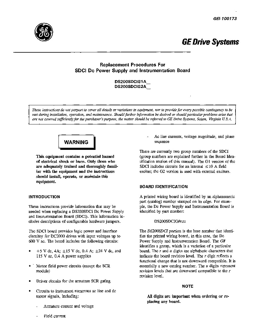
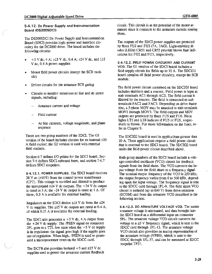
While it is important to be cognizant of this DS200SDCIGIAHB product offering's various normative and safe installation procedures, it is important to to identify many of the individual hardware elements that have been adopted into its assembly. One of the features of the DS200SDCIGIAHB model is that it is equipped with circuits to instrument AC lines and DC motor signals, such as field currents, armature currents/voltages, and more. This DS200SDCIGIAHB printed circuit board offers several unique hardware inclusions beyond these, and does make use of configurable hardware in its assembly for customization purposes. The customizable hardware in this DS200SDCIGIAHB PCB's assembly manifests itself in the form of manually-moveable Berg-type jumpers, with an additionally-installed DIP switch. For your convenience, the three total available jumpers in this DS200SDCIGIAHB product offering's assembly have been described in functional detail in the DS200SDCIGIAHB original instructional manual materials attached above. Voltage protections in the assembly of this DS200SDCIGIAHB product are handled by its typical varied inclusion of voltage-limiting hardware components such as rectifiers, diodes, and capacitors. Before making any final purchase decision on this DS200SDCIGIAHB printed circuit board, it is important to realize that this DS200SDCIGIAHB product's three significant revisions alter its originally-introduced performance specifications and dimensions from their base-revised statuses.


