About the DS200SHVMG1
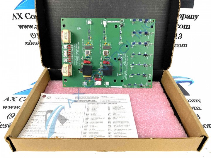
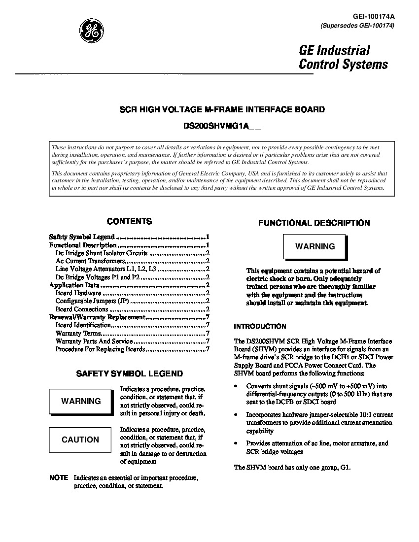
This DS200SHVMG1 Mark V Turbine Control System Series printed circuit board product offering from General Electric was originally manufactured for the specific functional role of an SCR High Voltage M-Frame Interface Board, as specified in the brief product description and pertinent original instructional manual materials made available above. The Mark V Series that this DS200SHVMG1 printed circuit board or PCB for short belongs to is something of a self-explanatory General Electric Mark product series, as its specific applications exists within steam or gas turbine control and management systems. The Mark V Series, while potentially applicable to newer-produced turbine applications, still must be considered obsolete as a whole; existing as a now-defunct legacy General Electric product series whose manufacture was discontinued due to a retailer-introduced functional series obsolescence and concurrent manufacturing discontinuation that took place in one of the many years beyond its initial release. With this being the case, this DS200SHVMG1 device's greater Mark V Series is still quite the desirable product series on the greater automated industrial marketplace, as it exists as one of the lastly-developed GE Mark product series to make use of the patented Speedtronic control system technology first seen with the rollout of the Mark I in the mid to later 1960s.
Hardware Tips and Specifications
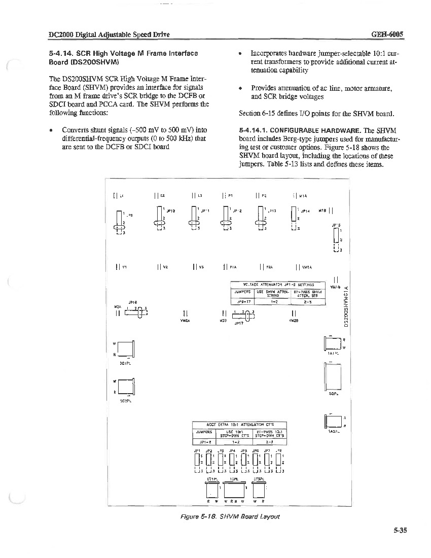
As with any General Electric Mark V Series product mae available to our extended new and reconditioned inventory here, this DS200SHVMG1 device's intended Mark V Series application is achieved by its normal assembly's acceptance of a specific series of specialized hardware components. The GE SCR High Voltage M-Frame Interface Board DS200SHVMG1 is a feature-rich board designed for high-voltage applications. This specific board provides an interface for signals from an M-frame drive’s SCR bridge to the DCFB or SDCI Power Supply Board and PCCA Power Connect Card. This is offered by utilizing 17 jumpers and 6 2-pin connectors, identified as JP1 through JP18 on the board surface. In addition, it supports 2 4-pin connectors for added flexibility. When operating the board with a current supply between 240 and 600 volts, it is recommended to place the jumpers in the bypass position. In this case, voltage attenuation is not necessary. For specific instructions on the jumper positions, please refer to the documentation provided by the board. Luckily enough for the sakes of this DS200SHVMG1 personalized product page here, this DS200SHVMG1 PCB's connectors are listed in the DS200SHVMG1 Data Sheet supplied above, contextualized by their specific transmission capabilities and the specific Mark V Series products that they interface with. For example, this DS200SHVMG1 Board's Power Supply Connectors include:
- The red IA1PL-1 Motor armature current (DC1) shunt differential VCO
positive output connector
- The white IA1PL-2 Motor armature current (DC1) shunt differential VCO
negative output connector
The Power Supply Board accessed by this DS200SHVMG1 PCB's two listed connectors is likely additionally available for repair and replacement right here at AX Control as a Mark V Series product. This DS200SHVMG1 PCB's two Power Supply Connectors do not make use of their own respective factory-printed nomenclature labels, as they are distinguished through use of their differing colorations as outlined once more in the above-attached DS200SHVMG1 Data Sheet above. During the replacement process, it is important to handle the GE SCR High Voltage M-Frame Interface Board DS200SHVMG1 with care. Before installing the replacement board, place both the old and new boards on a protective surface such as an EDS static protective wrapper. Take note of how the jumpers are configured on the old board. Remove a jumper from one set of pins and insert it over the corresponding pins on the new board to match the configuration of the old board. The dimensions of the board are 7 by 9.5 inches, and it features screw holes in all four corners for secure installation. When replacing the old board, utilize the same screw holes in the rack to install the replacement board, ensuring a proper and secure fit. For comprehensive installation and configuration details, please consult the relevant documentation provided with the GE SCR High Voltage M-Frame Interface Board DS200SHVMG1.


