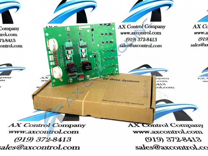
About the DS200SHVMG1AED
Greater Series Information
General Electric’s DS200SHVMG1AED is an SCR High Voltage M-frame interface board; this card was developed for the Mark V series of optional and replacement boards. As a member of that series, this interface board can easily be installed across a wide range of GE brand drives and exciters: The Mark V Series that this DS200SHVMG1AED printed circuit board belongs to is considered a now-obsolete legacy General Electric product series, due to its manufacturing discontinuation in the many years following its initial release. While this DS200SHVMG1AED product offering's greater Mark V Series is definable as a legacy product series, it is somewhat of a recently-developed product series given the fact that it exists as one of the final General Electric product series to make use of the patented Speedtronic control system technology. This DS200SHVMG1AED printed circuit board or PCB for short is not the original product of its functionality develops for General Electric's Mark V product series The original would be the DS200SHVMG1 parent SCR High Voltage M-frame Interface Board missing all three of the DS200SHVMG1AED product's significant product revisions.
Hardware Tips and Specifications
A number of voltage and conversion functions are provided by installing this board into a drive:
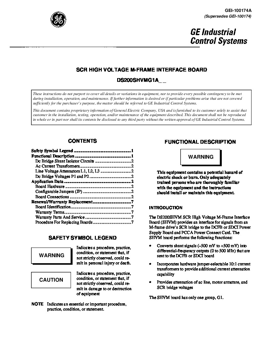
- After installing the card, a medium for interfacing the SCR bridge from the M-frame drive and the power supplies found in either the DCFB or SDCI board as well as the power connect card, or PCCA.
- Differential frequency outputs ranging from 0 to 500 kHz are produced by the card converting shunt signals ranging between -500 and 500 mV. All conversions of these signals are performed by DC positive and negative floating shunts in the voltage-controlled oscillator (VCO) circuits.
- Once converted, the differential frequency outputs are sent to the DCFB/SDCI board or the PCCA card. AC line currents on the board are provided a 10:1 current transformer attenuation.
- There are 17 configurable jumpers on board, allowing users to select attenuation rates.
Several connectors have been included in this DS200SHVMG1AED PCB's assembly for convenient and safe interfacing potential. These connectors all correspond to their own specific factory-printed nomenclature labels, and include:
- The CT1PL-1 L1 ACCT Current Negative Input Connector
- The CT1PL-2 L1 ACCT Current Positive Input Connector
- The CT3PL-1 L3 ACCT Current Negative Input Connector
- The CT3PL-2 L3 ACCT Current Positive Input Connector
These connectors exist specifically as the Connectors pertaining to this DS200SHVMG1AED PCB's L1 and L3 connection locations; this is only about half of the potential connections that can be established in the assembly of this DS200SHVMG1AED PCB, as many others are listed with their specific functions in the DS200SHVMG1AED instructional manual available above for your convenience
Installation and Replacement Tips and Specifications
Installation parameters provided with the DS200SHVMG1AED as well as the installing drive should be followed. Meeting these guidelines will protect the drive system from any accidental or avoidable damages:
- Instructions for installing the board and wiring all the components are available in the device’s manual and datasheet.
- Members of the Mark V series of boards were originally provided with technical support by General Electric, the manufacturer.
- Before making any final purchase decision on this DS200SHVMG1AED product offering, is is of crucial importance to realize that its originally-introduced performance specifications and dimensions have no doubt been impacted by this DS200SHVMG1AED PCB's possession of two functional revisions and an artwork configuration revision.


