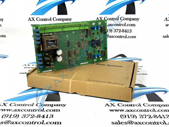
About the DS200SIOCG1A
This DS200SIOCG1A printed circuit board was originally designed and produced to exist as a member of trusted automated industrial retailer General Electric's Mark V Turbine Control System Series. As you have surely been able to ascertain by its full extended series title, the Mark V Series that this DS200SIOCG1A printed circuit board belongs to has specific applications in the management and control systems of compatible wind, steam, and gas turbine automated drive assemblies, and is considered a General Electric legacy series due to its eventual manufacturing discontinuation in the years following its initial release. This DS200SIOCG1A printed circuit board's greater Mark V Series, while a now-obsolete legacy series, is considered to exist as one of the final General Electric product series to make use of the patented Speedtronic control system technology. This DS200SIOCG1A PCB is better-definable through its true functional product description as a VME Stand I/O Board, although the original VME Stand I/O Board developed for placement in the Mark V Turbine Control System Series is the DS200SIOCG1 parent printed circuit board notably missing this DS200SIOCG1A product's A-rated functional product revision.
Hardware Tips and Specifications
As with any Mark V Series printed circuit board product offering, this DS200SIOCG1A PCB is accompanied by its own particular series of functionality-inducing hardware components and individual component specifications. The GE VersaModular Eurocard (VME) Stand I/O Board DS200SIOCG1A features five wire terminals that can connect to a maximum of 33 signal wires. It is also populated with one fuse and four 2-pin connectors. The wire terminal blocks on the GE VME Stand I/O Board DS200SIOCG1A are labeled TB-1, TB-2, TB-3, TB-4, and TB-5 on the board. The wires carry signals that are transmitted by the board or are received by the board during processing. The wires are held in place with screws that secure the wires in the terminals. Each terminal also has an identifier printed on the board. The previously-included DS200SIOCG1A-specific information was retrieved from a visual inspection of the device itself, given this DS200SIOCG1A PCB's attribution to the now-obsolete Mark V Turbine Control System Legacy Series. With this in mind, the DS200SIOCG1A functional product number can be considered a good source of original DS200SIOCG1A Board hardware information, revealing important details in several functional naming chunks. Some of the DS200SIOCG1A Board-specific information detailed through the DS200SIOCG1A functional product number include this DS200SIOCG1A PCB's:
- Normal Mark V Series assembly
- Domestic original manufacture location
- SIOC functional product abbreviation
- Normal style of PCB surface coating
- Group one Mark V Series product grouping
- A-rated functional product revision
This DS200SIOCG1A printed circuit board is equipped with its own set of instructional manual-explained installation requirements and suggestions. Each of these manual-printed instructions is important to follow, as this static-sensitive DS200SIOCG1A device can be damaged by improper contact, and may even possess potentially-lethal surface voltages. When you replace the board you must first tag each wire connected to a terminal with the ID assigned to the terminal to which it is attached. Then, when all power is removed from the board, you can loosen the screws that secure the wire in the terminal. Check to make sure the tag is attached to the wire and that is has the right terminal ID written on it. Bend the signal wires out of the way so you can remove the old board and install the replacement board. When you are ready to reattach the signal wires, insert the bare portion of the wire into the terminal and hold it in place with one hand. Use the other hand to tighten the screw with a screwdriver. Pull on the wire to check if it is secure and will not come out on its own at all.


