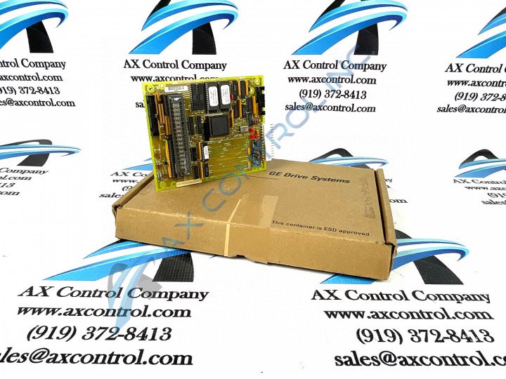
About the DS200SLCCG2ACC
The DS200SLCCG2ACC module works as a LAN Communications module within GE’s Mark V systems. The Mark V Series was one of the later Speedtronic control systems for industrial gas or steam turbines released by General Electric, and one of the few that could be used for either simplex or triple modular redundant systems. Our company maintains stock of many replacement parts for Speedtronic systems, including multiple versions of this LAN Communications module; be sure to order the correct version for your application, duplicating your previous board id perfectly. The exception to this genral rule would be if you need to replace EPROMs at U6 and U7; this board typically ships without these EPROMs since normal practice is to move these ICs from the old board to the new. If you need replacement of the chips that carry software information, please order a DS215 board instead of a DS200.
Hardware Tips and Specifications
The DS200SLCCG2ACC board mounts on an SDCC board within the Mark V system, and makes use of its own series of necessary and specific hardware components and component specifications. The SLCC and SDCC boards interface together within the Mark V Series automated drive assembly using the KPPL connector. The DS200SLCCG2ACC board is populated with a 16-digit alphanumeric display, along with multiple integrated chips, berg jumpers, wire jumpers, resistors, resistor network arrays, capacitors, and diodes. Three total jumpers are included in the internal assembly of this DS200SLCCG2ACC LAN Communications Module; accompanied by the respective factory-printed nomenclature labels of JP1, JP2, and JP3. The JP1 and JP3 jumpers in the assembly of this DS200SLCCG2ACC PCB are included for General Electric factory testing purposes, and should never be accessed by the prospective DS200SLCCG2ACC LAN Communications Card buyer. The JP2-labeled jumper in this DS200SLCCG2ACC PCB's assembly was included for the selection of 486 local bus speeds.
The board also has several connectors and has been drilled at each corner to accept standoffs for mounting. Some of the various connectors in the assembly of this DS200SLCCG2ACC PCb include the ARCNET STCA COREBUS Connector, the COM1 Terminal Interface Monitor Connector, the J1 and J3 STCA Bus Connectors, and the IDE and COM2 Connectors, which typically go unused during normative function of this DS200SLCCG2ACC PCB. Be sure to turn off power to the drive before removing the board or its connections. This limits the possibility of equipment damage. Be sure to follow the same procedure before reinsertion of the board within the drive or reconnection of circuits. It is recommended you label cables before disconnecting them to simplify reconnection.


