❮

❯


DS200SPCBG1A
- 4.88 (17)
- Click a star to rate this product
- 4.88 (17)
- Click a star to rate this product
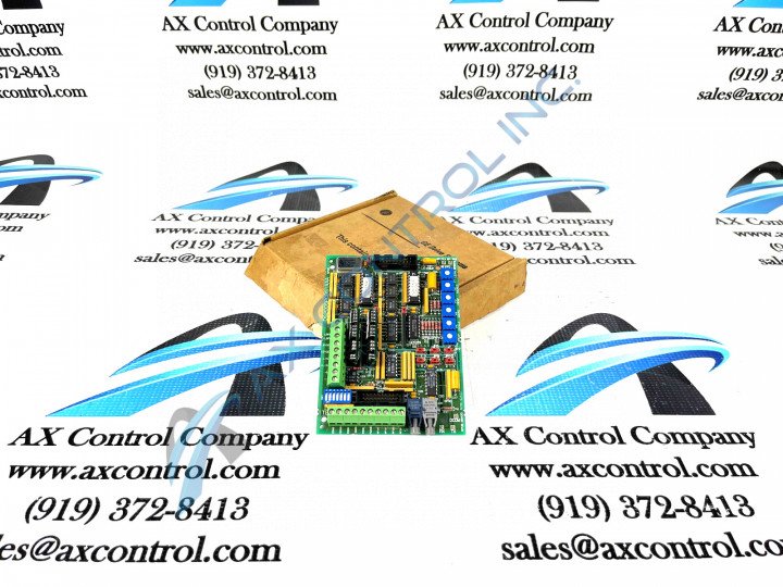
The GE DS200SPCBG1A is a Signal Process Board manufactured by GE Industrial Solutions for the Mark V Series.
AVAILABILITY:
IN STOCK
SHIPS TODAY
- Part Number: DS200SPCBG1A
- SKU: DS200SPCBG1AGBTC
- Manufacturer: GE Boards & Turbine Control
- Series: Mark V DS200
DS200SPCBG1A Technical Specifications
| Manufacturer | GE General Electric |
| Series | Mark V |
| Part Number | DS200SPCBG1A |
| Functional Description | Multi-Bridge Signal Processing Board |
| Instruction Manual | GEI-100166 |
| Functional Acronym | SPCB |
| PCB Coating | Normal Coating |
| Functional Revision 1 | A |
About the DS200SPCBG1A
This DS200SPCBG1A printed circuit board product offering from General Electric was, as described above, originally manufactured for a specific placement in the Mark V Turbine Control System Series automated drive assembly as a Multi-Bridge Signal Processing Board. A rather self-explanatory General Electric Mark product series; the Mark V Series that this DS200SPCBG1A printed circuit board or PCB for short belongs to has specific applications in the control and management systems of popular and compatible steam, gas, and even wind turbine automated drive assemblies, although its does exist as a now-obsolete legacy product series discontinued due to a manufacturer-identified obsolescence in one of the many years past its initial Mark Series release. The Mark V Turbine Control System Series containing this DS200SPCBG1A product is not a wholly-undesirable product series on the general automated industrial marketplace, despite its complete and total obsolescence. This is likely due to the fact that the Mark V Series is one of the lastly-developed GE Mark product series to make use of the patented Speedtronic control system technology first introduced with the rollout of the Mark I in the later 1960s.
Hardware Tips and Specifications
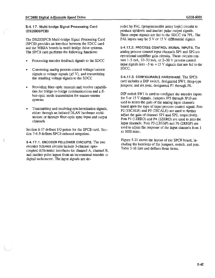
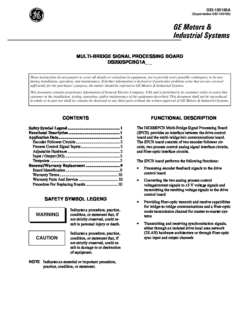
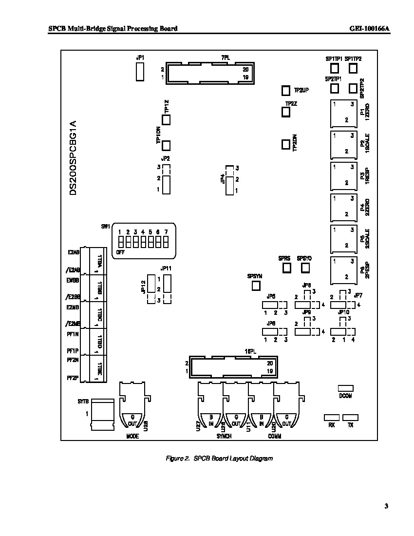
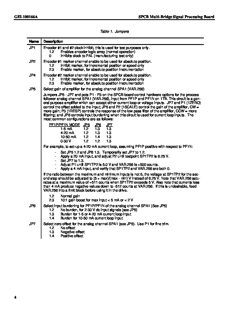
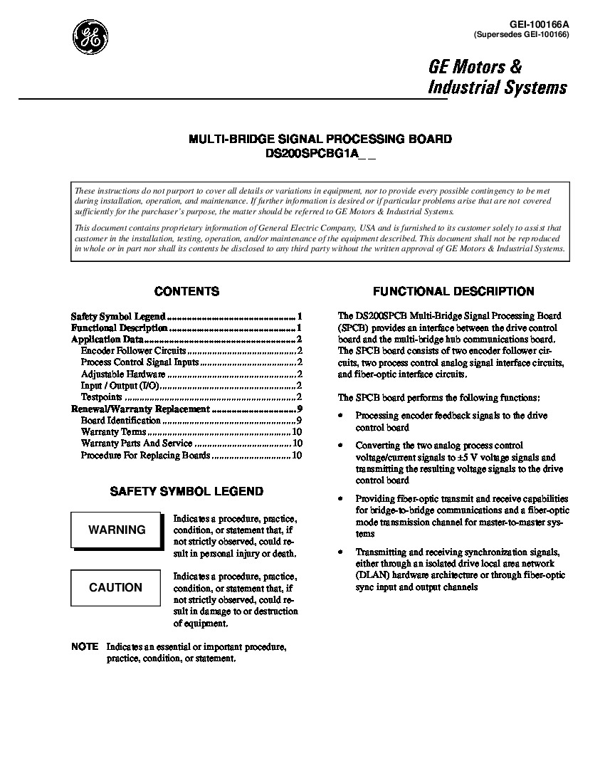
The GE Multi-Bridge Signal Processing Board is DS200SPCBG1A is an interface between the drive control board and the multi-bridge hub communications board. The board processes encoder feedback signals to the drive control panel and also provides the fiber optic network capabilities for bridge-to-bridge or master-to-master network communications. For starters, this DS200SPCBG1A PCB is not the originally-produced device of its specific Mark V Series functionality; that would be the DS200SPCBG1 parent Multi-Bridge Signal Processing Board missing this DS200SPCBG1A Board's singular A-rated functional product revision. One DIP switch labeled SW1 has been provided to the normal assembly of this DS200SPCBG1A PCB; this switch is used to configure encoder inputs for signals within the voltage range of 5 to 15 V. In addition to this DS200SPCBG1A Device's singular switch, its normal Mark V Series assembly makes use of several other pieces of customizable hardware such as Berg-type manually-moveable hardware jumpers and six pots; which range with different factory-printed nomenclature labels from P1 to P6. Luckily enough for the sake of this DS200SPCBG1A personalized product page here, this DS200SPCBG1A Mark V Series legacy product is stored with some sparsely-available instructional manuals online; manuals that detail the various connectors in this DS200SPCBG1A PCB's normal Mark V Series assembly. For example, this DS200SPCBG1A PCB's drive synchronization connectors include:
- The 1-pin SYNC Drive non-inverting synchronization signal connector
- The 2-pin /SYNC Drive inverting synchronization signal connector
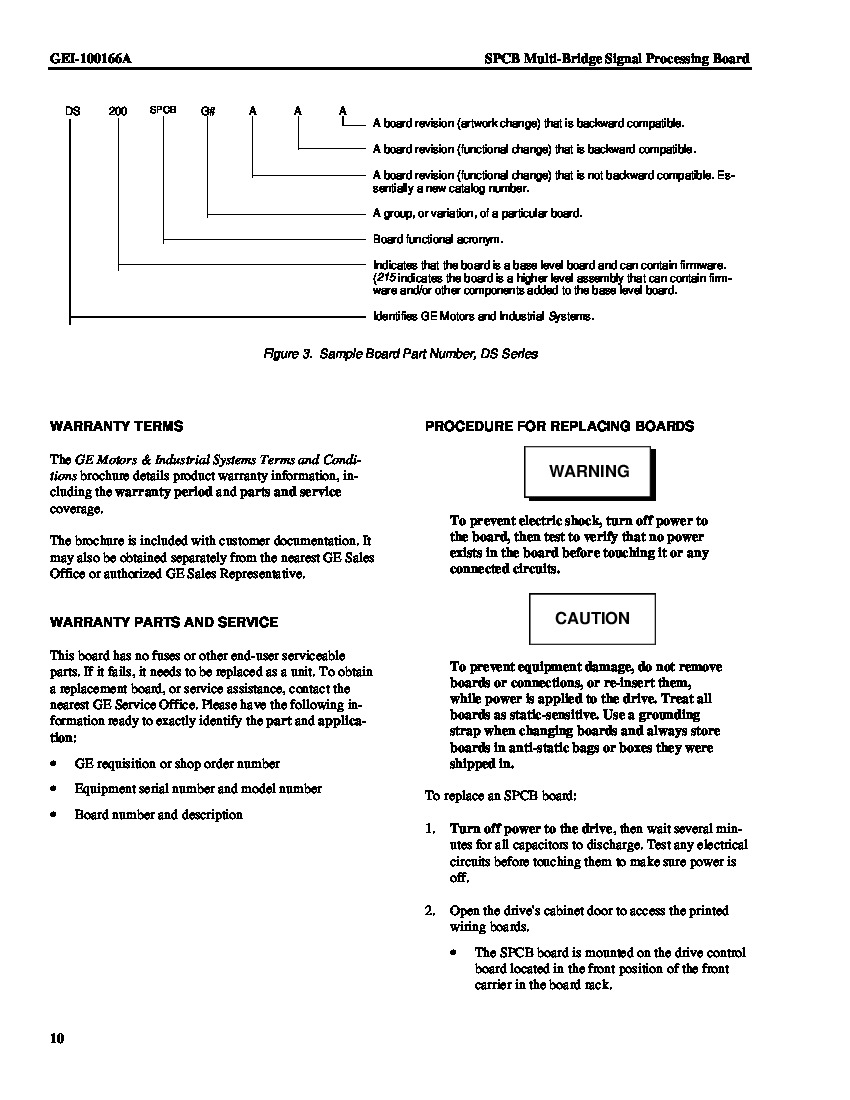
Each of the previously-listed connectors in this DS200SPCBG1A PCB's normal Mark V Series assembly has been named through a combination of thier pin numbers, their factory-printed nomenclature labels, and finally the style of signal that they were specifically designed to transmit. A ribbon cable provides the connection between the board and the drive control board. The drive control board and the GE Mark IV PC Board are both installed in the drive circuit board cabinet. When you replace the DS200SPCBG1A, you must disconnect the ribbon cable from the defective board and reinstall it in the replacement board. However, you must take special care when you disconnect and reconnect the ribbon cable. The ribbon cable is composed of multiple fine wires and they are terminated on both ends with a connector. Each of the fine wires carries a signal but is subject to break or disconnect from the connector and the installer might be unaware of the defect. Treat the ribbon cable carefully and only use your hands to grasp the connector when you connect or disconnect the ribbon cable. Never attempt to disconnect the cable by tugging on the ribbon cable. If at any point you contact a service representative you can shorten the call by having all the information available to identify the board. You should write down the information when you first take possession of the board, however, if you cannot find the written record of the board, you can locate the identifying information on the board.
Frequently Asked Questions about DS200SPCBG1A
What type of interface does DS200SPCBG1A provide?
How are input signals decoded on a DS200SPCBG1A board?
What adjustable hardware is included with DS200SPCBG1A?
How do I get the manual for DS200SPCBG1A?
Reviews For DS200SPCBG1A
Internal Review
(5.0)The GE DS200SPCBG1A Signal Process Board is a compact but critical PCB used in turbine control applications. With manufacturer manuals and documentation available it is a user friendly process to modify the on-board jumpers, dip switches, and potentiometers to the application specific settings needed when installing in a system. Likewise, the terminal strip configuration on the DS200SPCBG1A is straightforward and labeled clearly for accurate wiring. Overall, the DS200SPCBG1A is a critical yet easy to install board and deserves a rating of 5 Stars - AX Control Lead Technician
Repair Services For DS200SPCBG1A
| Type | Lead Time | Price | Action |
|---|---|---|---|
| Repair Service | 1-2 weeks | $175 |
Our highly skilled technicians can repair your DS200SPCBG1A. All of our repairs come with a 3 Year AX Control Warranty. Please contact us for additional information about our repair process. To receive the repair pricing and lead time listed above please process your repair order via our website. The following repair options may be available upon request:
- 48-72hr Rush Repair
- Detailed Repair Reports
- AX Control Certificate of Warranty
AX Control Warranty Info
All products we sell are backed by our unparalleled warranty. A warranty certificate will be provided with your order upon request.
| All PLCs, HMIs, and Turbine Control Boards: | 3 Years |
| All AC/DC and Servo Drives: | 2 Years |
| All Motors: | 1 Year |
DS200SPCBG1A Manuals, White Papers, Data Sheets, and Troubleshooting
- DS200SPCBG1A Data Sheet GEH-6005.pdf
- DS200SPCBG1A MULTI-BRIDGE SIGNAL PROCESSING BOARD Intro.pdf
- DS200SPCBG1A MULTI-BRIDGE SIGNAL PROCESSING BOARD Drawing.pdf
- DS200SPCBG1A MULTI-BRIDGE SIGNAL PROCESSING BOARD App Data.pdf
- DS200SPCBG1A MULTI-BRIDGE SIGNAL PROCESSING BOARD Warranty Replacement and Renewal.pdf
- DS200SPCBG1A MultiBridge Signal Processing Board GEI-100166A.pdf


