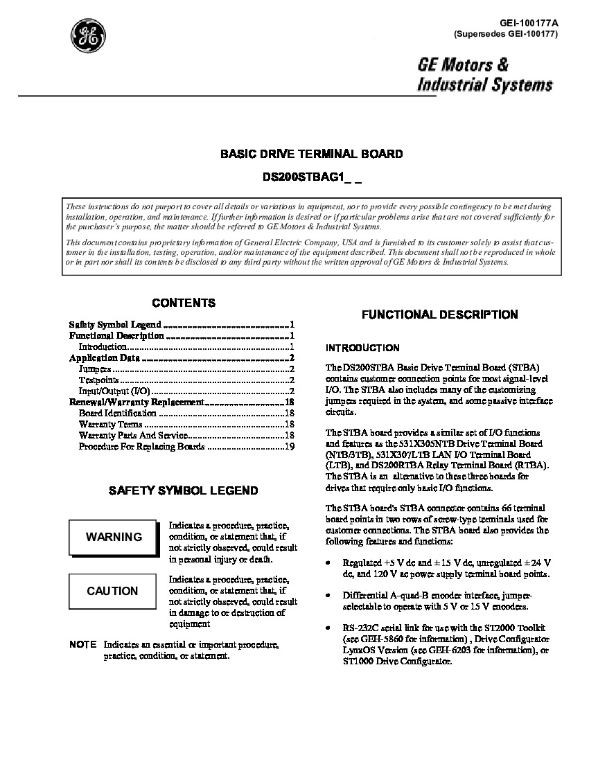
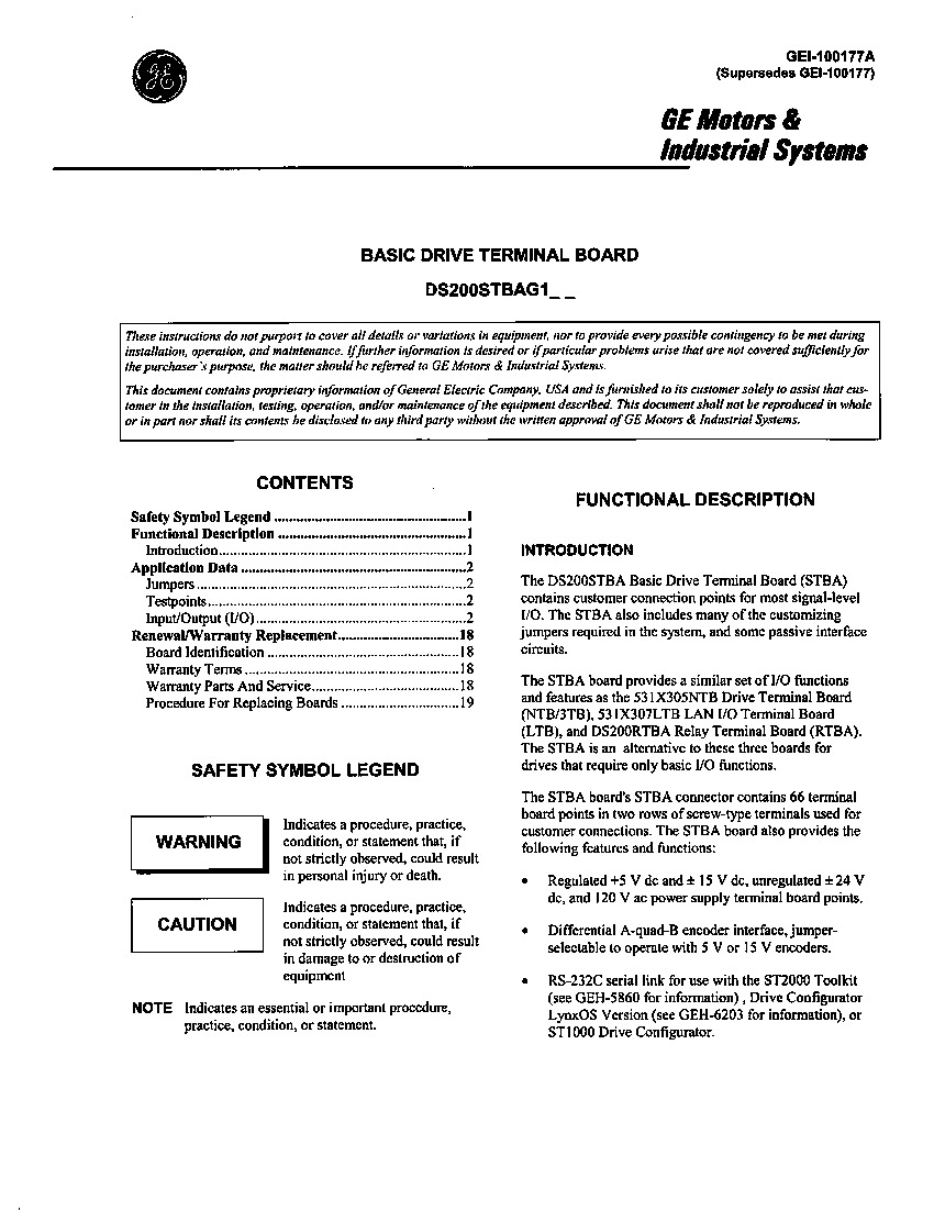
About the DS200STBAG1
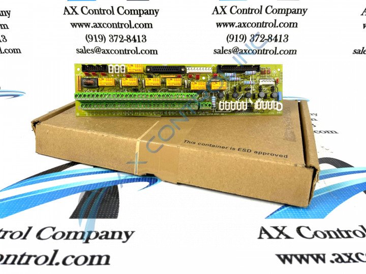
The GE Basic Drive Terminal Board DS200STBAG1 provides connection points for I/O signals to its greater Mark V Series automated drive assembly, as discussed above. This particular DS200IIBDG1ADA printed circuit board product offering, as alluded to above, was originally designed and manufactured by General Electric, who incorporated their patented Speedtronic control system technology into this DS200IIBDG1ADA AC/DC Terminal Board. This DS200IIBDG1ADA printed circuit board or PCB for short is the originally-developed product of its specific functionality to be developed by General Electric, as evidenced by its DS200IIBDG1ADA functional product number's declination of any trailing revision-indicating digit.
Hardware Tips and Specifications
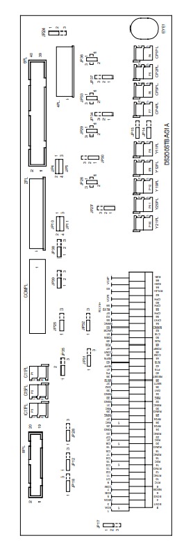
The DS200STBAG1 is easy to replace if a malfunction occurs. Always remove power to the drive. Failure to do so might cause damage to the drive and it might create a safety hazard if you attempt to touch the board. Also, you must disconnect all cables from the board. A procedure must be followed to remove ribbon cables because they are fragile; use one hand each to hold the connector on the ribbon cable and one hand to hold the connector on the board. Carefully pull the connectors apart.For other cables that feature tabs, pull the tab to release the cable. To remove connectors CPxPL, YxxPL, CIxPL, press down on the latch that locks the connectors in place and pull out the connector. Terminal board connectors are held in place with screws. Remove the screws and pull out each signal wire individually. To remove the DS200STBAG1 board, hold the board with two hands and gently pull out the board. Be careful not to touch the side of the cabinet with the board or touch against any other boards or metal structures in the cabinet. Note the jumper setting on the old board and carefully transfer them to the new board. Note that if the replacement board is a newer model, the components on the board might be in different locations and the board might have different components. How ever, compatibility is maintained between the older and newer versions. While the various installation procedures important to proper maintenance of the DS200STBAG1 product are well-documented in this DS200STBAG1 product's original instructional manual materials, so too are some of this DS200STBAG1 PCB's recognizable hardware components. Some of the basic hardware additions identifiable in this DS200STBAG1 Terminal Board's assembly include:
- 3 separate styles of power outputs
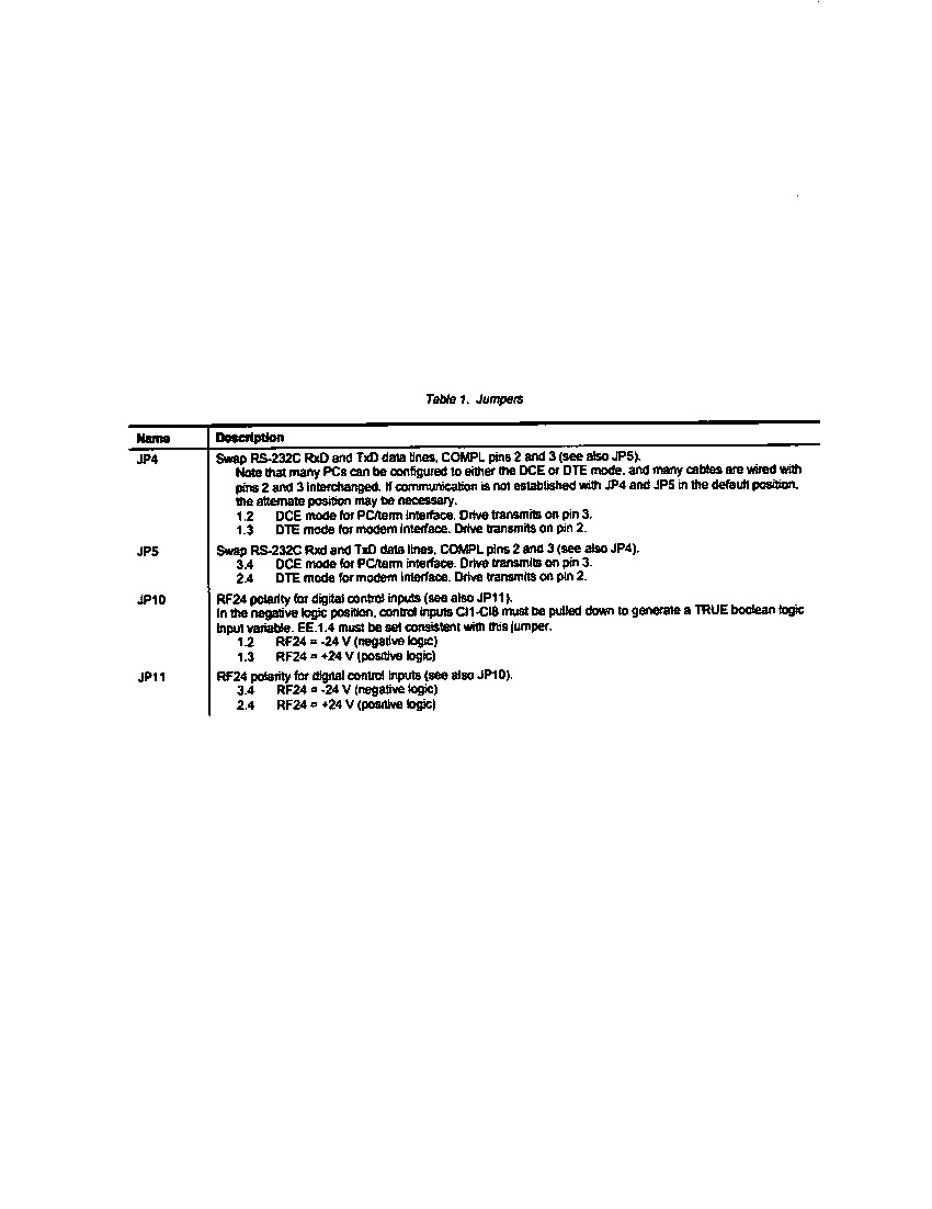
- Manually-movable hardware jumpers
- Configurable control inputs
- Both an encoder and RS-232 interface
- Basic voltage-limiting hardware components, including resistors and capacitors
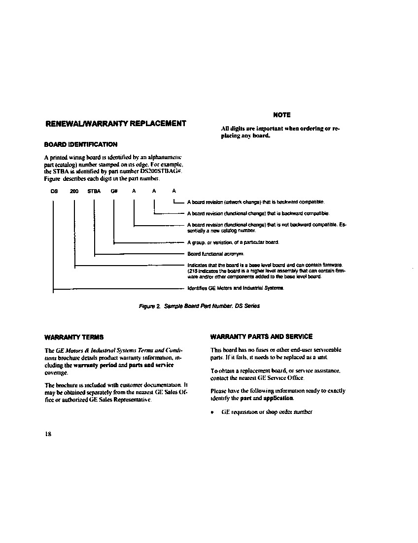
Before making a final purchase decision on this DS200STBAG1 product offering, it is important to realize that this DS200STBAG1 PCB exists as a highly-customizable General Electric product, given its possession of over 40 manually-moveable hardware jumpers. This DS200STBAG1 PCB's DS200STBAG1 functional product number is considered an additional source of strong DS200STBAG1 board hardware information, describing this DS200STBAG1 product's normal Mark V Series assembly, STBA functional product abbreviation, and other crucial hardware specifications as detailed in the manual documentation provided above.


