About the DS200STBAG1A
Hardware Tips and Specifications
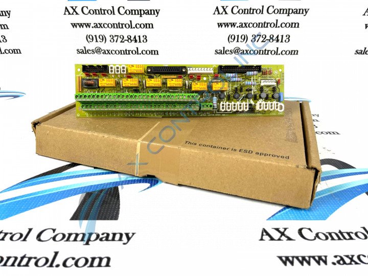
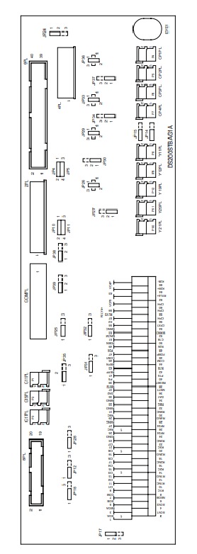
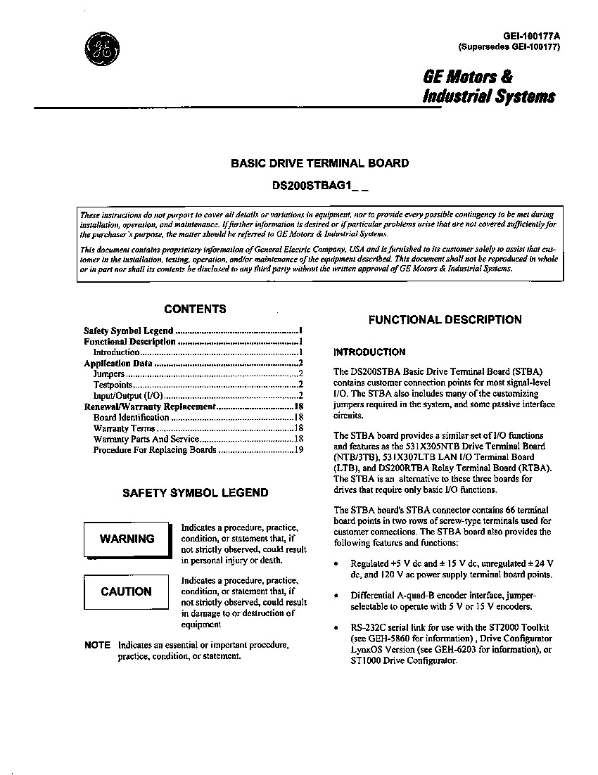
The GE Basic Drive Terminal Board DS200STBAG1A provides connection points for I/O signals. The DS200STBAG1A has a series of four connectors that are only for factory use. The connector identifiers are CP1PL, CP2PL, CP3PL, and CP4PL. They provide 115 VAC power for the panel and they are used for testing purposes at the factory. The board has a RS232C serial port that is useful for connecting to configuration software loaded on a laptop computer or other device. You can connect an appropriate cable from the board to the serial connector on the laptop. If you have loaded the software on the laptop you can configure the board. Make sure the serial port on the laptop is configured properly to connect to the DS200STBAG1A board. The four factory-use-only connectors available to the assembly of this DS200STBAG1A PCB are by no means the only connectors made available to its assembly, as it features numerous other connectors included for valuable interfacing within the Mark V Series automated drive assembly, as explained in the DS200STBAG1A instructional manual attached above. This is also true of the series of over twenty-five manually-moveable hardware jumpers in this DS200STBAG1A product offering's assembly.
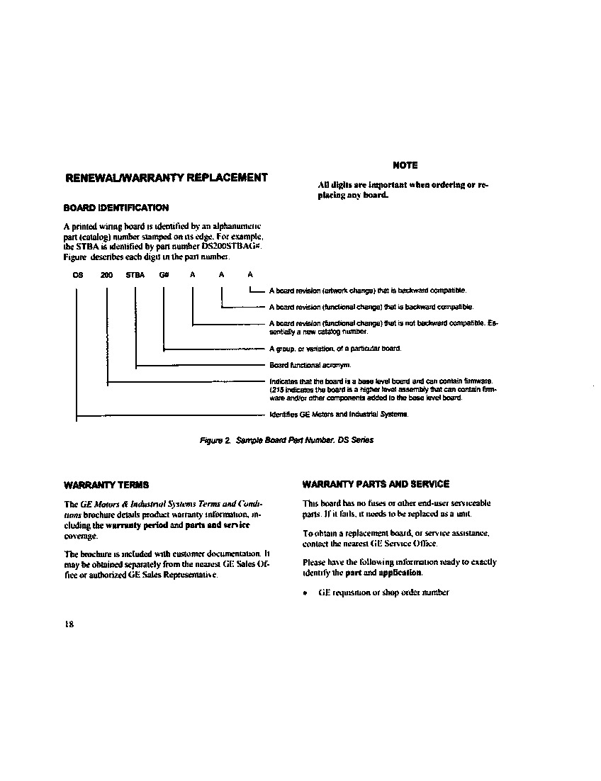
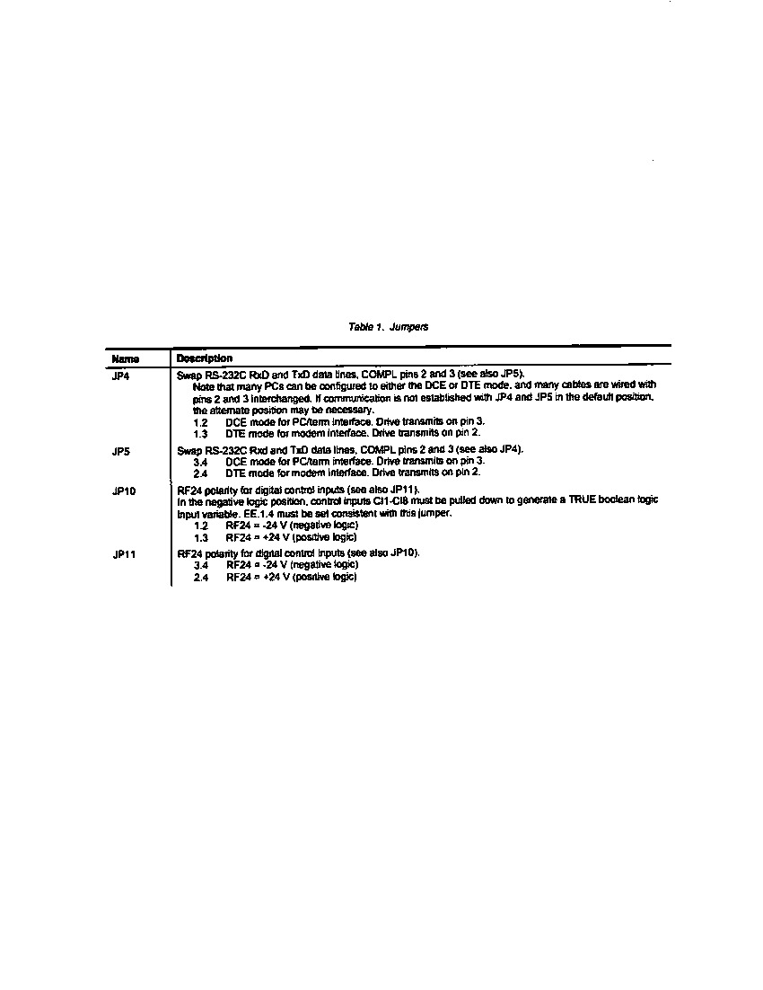
The board contains multiple styles of jumpers. Some are for factory use only and some enable you to configure the board. For example, JP4 and JP5 configure the RS232C connection. Use pin 1 and pin 2 on JP4 in order to maintain a connection to a laptop. Use pin 3 and 4 on JP5 for connection to a laptop. However, if you are unable to establish a connection, you might try to move the pins to the other position as a troubleshooting measure. If you are unable to connect to the laptop, make sure you connected the cable to the right port on the laptop. Also, check the configuration of the serial port and also disconnect the connector and reseat the connector to ensure it is fully seated. The DS200STBAG1A functional product number is an additional source of DS200STBAG1A board-specific hardware information, exposing details such as this DS200STBAG1A PCB's:
- Normal Mark V Series assembly version
- Domestic location of original manufacture
- STBA functional product abbreviation
- Normal PCB coating style
- Group one Mark V Series grouping
- A-rated functional product revision
The normal style of PCB surface coating that has been applied to this DS200STBAG1A product exists as a thick rudimentary layer of basis daily wear and tear circuit board protection that envelops and protects individual DS200STBAG1A board hardware elements on a functional priority basis. The A-rated functional product revision made to this DS200STBAG1A Basic Drive Terminal Board's assembly improves the basic performance specifications and overall functionality of the DS200STBAG1A model PCB without making any significant sacrifices or durability or aesthetic quality. As detailed once more in this DS200STBAG1A device's originally-printed instructional manual materials, this DS200STBAG1A device ships with the COMPL Connector attached; a connector with the specific function as existing as an RS-232 serial communications link for communications with the Mark V Series' Drive Configuration Tools.


