About the DS200STBAG1ADC
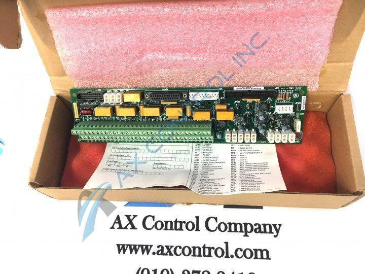
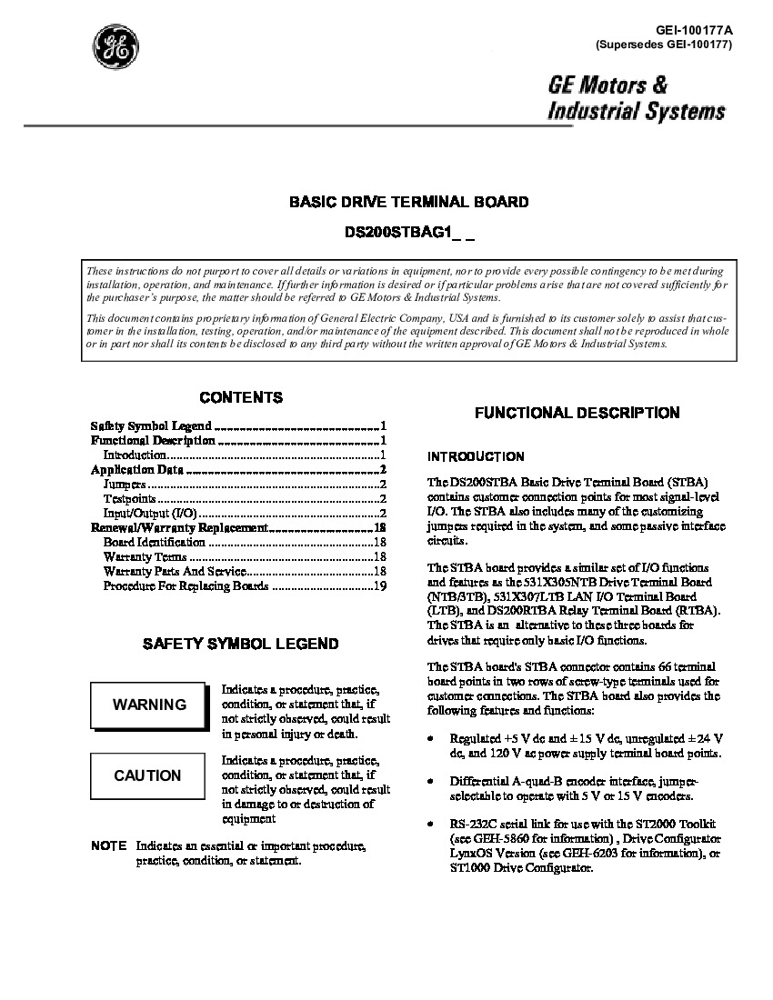
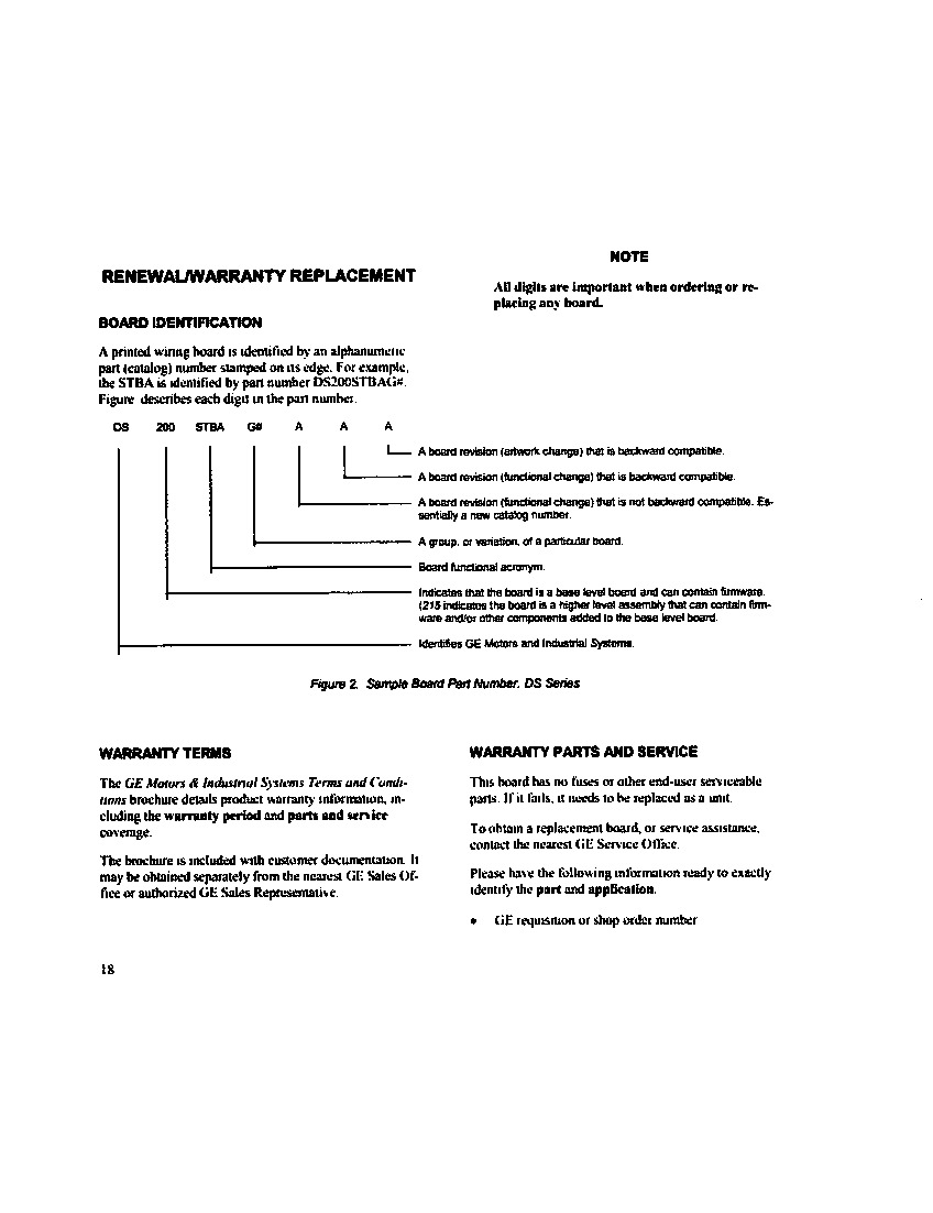
The GE Basic Drive Terminal Board DS200STBAG1ADC provides connection points for I/O signals. Multiple revisions of the DS200STBAG1ADC exists and each is an improvement over the former versions in terms of reliability, usability, and cost effectiveness. This particular DS200STBAG1ADC PCB exists as a three times-revised version of the original DS200STBAG1 Basic Drive Terminal Board, making use of an A-rated functional product revision, a D-rated functional product revision, and a C-rated artwork configuration revision. This DS200STBAG1ADC Basic Drive Terminal Board's Mark V Series has originally-intended applications in the control and management systems of steam, wind and gas turbine automated drive assemblies, and is considered a legacy series as it has been discontinued for manufacture in the years since its initial release. While a General Electric legacy series, the Mark V is also one of the final General Electric product series to feature their patented Speedtronic control system technology in its various products; a technology that was first introduced with the rollout of the Mark I in the late 1960s.
Hardware Tips and Specifications
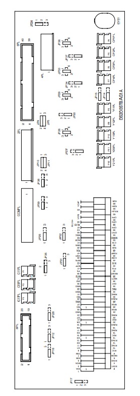
As with any product in General Electric's extended catalog of Speedtronic technology-led control system products, this DS200STBAG1ADC Basic Drive Terminal Board makes use of a specific series of hardware components to attain its originally-intended functionality. Given the fact that this DS200STBAG1ADC Basic Drive Terminal Board is populated with revisions outranking the ABB specification, it is not considered to possess any sort of diagnostic testpoint in its assembly, although its face is populated by several Mark V Series-standardized hardware components included for voltage limitation purposes, such as as capacitors and resistors. Several corners of this DS200STBAG1ADC product offering's base circuit board have been drilled for convenient installation purposes, with each factory-drilled hole insulated in observance of potentially-present damaging surface voltages and static electricity. Connectors CP1PL through CP4PL are only for factory use only. They are used for supplying 115 VAC power to the board in a bench environment for testing purposes. Y19PL, YP20PL, and Y21PL are connectors on the board that are also only for factory use. The three connectors enable testing of the brake control circuits at the factory.
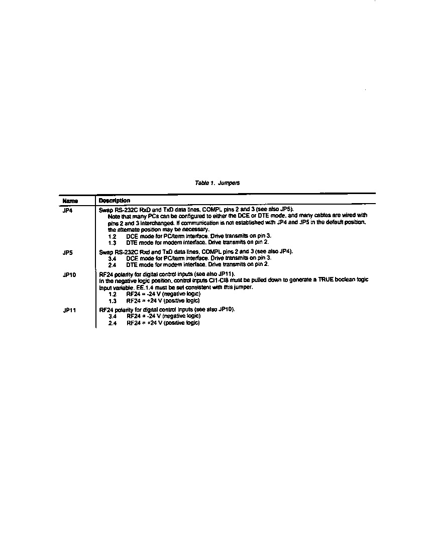
The DS200STBAG1ADC uses multiple jumpers to enable the user to set up various configuration options. Both JP4 and JP5 are used to configure the RS232C serial port for communications. One position is used for modem communications and one position is used for serial communications to a laptop. If you find that you are unable to successfully initiate serial communication to a laptop, you might switch the pin positions of JP4 and JP5 to see if the signals are compatible with the laptop. All of the hardware elements made available to the normal assembly of this DS200STBAG1ADC printed circuit board should be at least somewhat protected through the thick rudimentary protective layer afforded to this DS200STBAG1ADC PCB through use of its normal style of printed circuit board coating, which envelops and protects individual DS200STBAG1ADC base board elements on a functional priority basis. Before making a final purchase decision on this DS200STBAG1ADC Mark V Turbine Control System Series product, it is crucial to understand that its originally-introduced performance specifications and dimensions have no doubt been altered as a function of its possession of an extended three-fold revision history.


